
Nachtfee
Acryl
Console repair
Transformer
Substitute
(Ersatz)
Page initiated on 14 September 2023
Current status: 29 September 2023
Chapter 7
Chapter 8
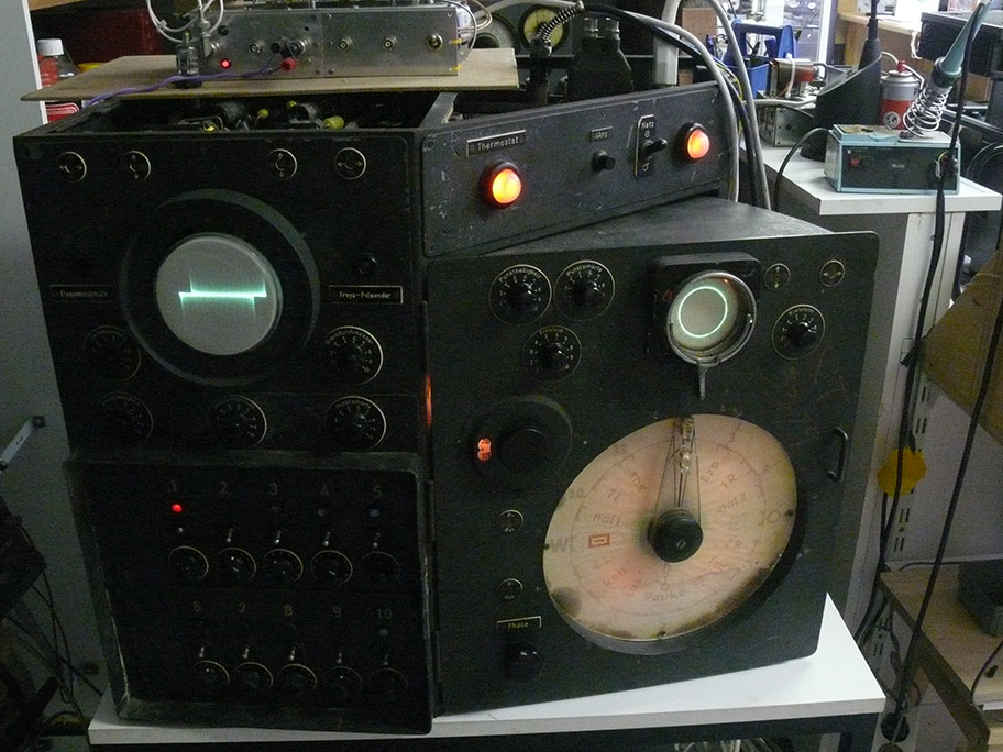
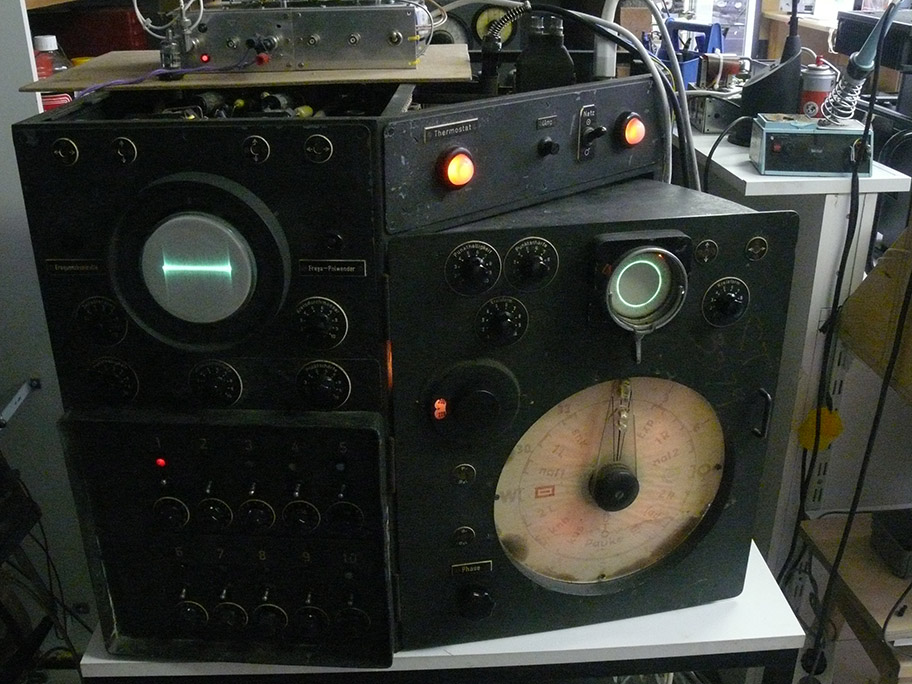
Before we went on holidays last summer, we encountered out of the blue
a sudden breakdown of our Nachtfee console.
The neon indicator-lamp extinguished and the 4 A fuse was blown (an old 2012 photo)
Before we left, there wasn't enough time to approach the failure
but
last Monday I had the mood to go for it.
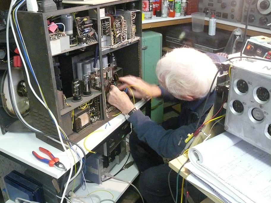
being alone in the museum premises, it wasn't an easy job, but finally a traced what causes the failure:

The corpus delictum is the transformer on the left-hand side
Somewhere in 2012 Dick Zijlmans managed to get this transformer re-wounded, as it showed an insulation problem in the 12 V transformer against ground; when the CRT high tension was exceeding the level of ca. 900 V.
It performed thereafter rather well, up to June 2023.
![]()
Reproducing my notebook from 16.4.2012
We notice:
HRP2 is the dual beam CRT (4 V)
RFG 5 is the 1.5 ... 2 kV CRT High Tension (HT) (6.3 V)
LB 2 is the circular CRT display acting as a control tube, showing the received IFF signal returning from our simulated aircraft system FuG 25a (12.6 V)
My first and main concern was: how can we cope with this essential situation, as Nachtfee cannot be operated without the control screens!
However, of course, I discussed my concern first with Hans Goulooze; whom else?
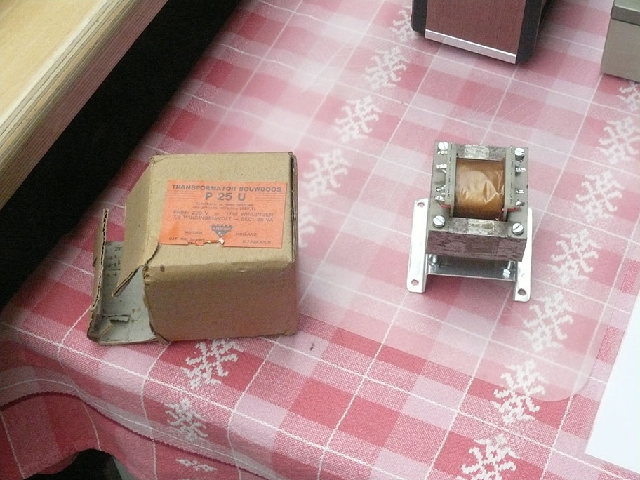
Out of the blue, Hans found a unique transformer kit of the 1960s maybe -70s, somewhere hidden in his own workshop:
![]()
This superb kit is just what one might demand for:
The centre core is build as primary 220 (230V AC) coil. It is necessary to reduce reduce the winding number for some percentage.
I must admit, that I never before knew such a transformer kit.
![]()
This page is showing some of its specs
Hans possessed the P 25 U version
providing enough winding space.
We only have to take care of winding the secondary windings
Hans re-calculated it for 230 V versus genuinely 220 V ac primarily voltage supply
We have to provide the next filament voltages: 6.3 V (RFG 5) and 12.6 V (LB2) as well as 4 V for the dual beam CRT.
![]()
It is quite evident that the construction of the transformer core has been constructed quite handsome,
easy to dismantle when necessary.
![]()
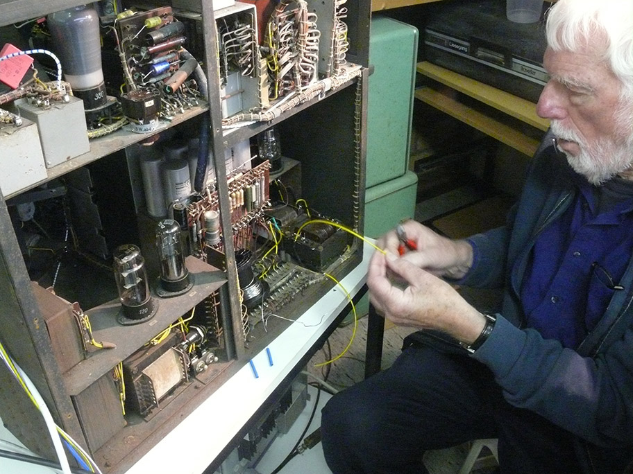
Hans once was engaged in the late 1960 up to the 1970s in winding special transformers for application in satellites
His winding rig is a very versatile tool for winding transformers.
Mylar insulation tape is important, as we deal with quite high voltages between some coil-sections.
![]()
The Mylar tape has to be fit with some care, albeit that the tape itself is quite resistive mechanically
Insulation between the three winding groups is essential;
as between the RFG 5 filament and the LB2 filament can exists > 2 kV ac voltage!
The other two groups LB 2 and HRP2/10/... are that critically versus one-another.
![]()
Maybe not entirely necessary, but providing a classical look, this old oil-type tape is in our historical context looking more or less genuine
The winding counter is essential because when one like to correct proper winding you have to go back some and then book-keeping the correct winding-number can only be managed by means of a direct spil counter.
![]()
Starting with soldering the 6.3 V coli-winding
Please notice the tiny red silicon insulation tube.
Luckily for us - the wire can easily be soldered without any difficulty.
One may wonder why I have chosen for implementing this transformer subject into our Acryl Air display recon.
The reason simply is, that without this transformer replacement, the Nachtfee subject has to be terminated definitely.
As the Nachtfee console display is essential in the entire reconstruction and its virtual operation!
(7) (since 22 September 2023)
![]()
Today the 21 September 2023, we have finished the newly wound transformer endeavour
For it we have to complete soldering the core-wires at their according taps
![]()
Considering it a bit more in detail
![]()
Now viewing it differently
![]()
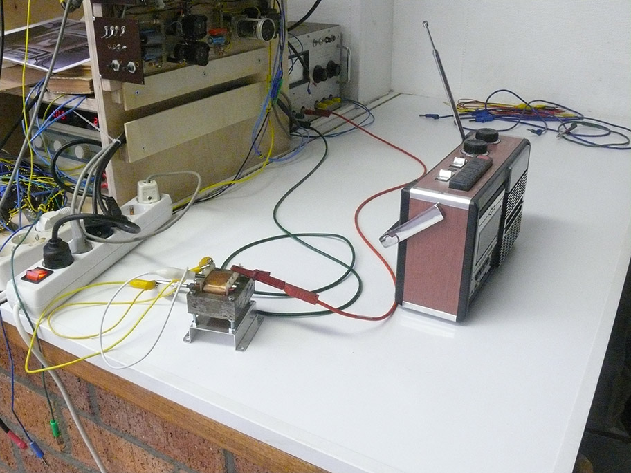
Hans Goulooze proposed rightly, that we first should consider whether the coils were supplying their correct output voltages
The metal core being not optimally mounted together, thus leaving a bigger core air-gap than necessary.
But, we do not load the transformer in this configuration, we supplied instead of 230-240 V only ca. 100 V ac
We can read off the Fluke scale 3.02 V ac
Do we multiply this by a factor up to 230-240 V we actually measure 6.3 - 6.4 V which is just what we want to achieve.
![]()
The next essential step is to measure the actual leakage between the primary coil and the newly fit windings for 4 - 6.3 and 12.6 V filament applications
These winding all will be loaded at say 2 kV (later increased to 4 kV) HT for the CRTs within the Nachtfee Console, albeit that the 6.3 V is to be used for the HT power-supply.
![]()
Viewing our new test set-up a bit differently
![]()
Now we have connected between the primary and the interconnected secondary wires
We measured ca 6 µA leakage current at a voltage across of 4 kV dc.
Not the slightest indication of sparking or the noise of it was encountered (heard).
![]()
Now a slightly different configuration have been introduced and we connected the 6.3 coil-windings onto the primary coil and measured the leakage current
There was not real difference observed!
![]()
Now we loaded the 6.3 winding and loaded it with the RFG 5 filament as will be the case within the Nachtfee Console
The result was that it performed perfectly well, according our desire!
Conclusion of today's experiments: Unexpectedly we came to the curious conclusion: that it is quite likely that the leakage measured being not caused by the leakage between the windings - but is mainly due to the hygroscopic phenomenon of the Nylon-like coil body; as there does not exist a difference between the leakage current measured between boarding (adjacent) windings, which should be expected.
Hans ,whom was engaged, as an employer, in quality management at a Satellite technology producing company.
He told me that on the long run Nylon (alike) insulation properties tend to be influenced by humidity over many decades.
Hans' Amroh transformer kit was obtained probably in the 1960s, and has never been stored - in a humidity controlled environment - but somewhere in his likely not heated hobby room, for more than a century (he even lived, for quite a while, onboard a boat).
(8) (since 29 September 2023)
Today 28 September 2023
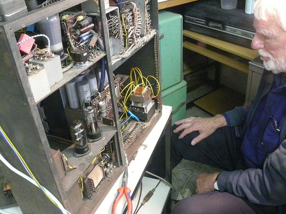
Hans Goulooze started with the endeavour to refit the transformer substitute
inside our Nachtfee Console.
On the left-hand side the genuine transformer kit box; on the right-hand side the our new transformer placed upon a pedestal
which four hole should match to the old screws of the faulty genuine transformer
As to keep this genuine component inside the Nachtfee Console.
1.

Viewing our transformer a bit differently
The text at the label of the cardboard box is:
Transformator bouwdoos (Transformer kit)
P 25 U (Type P 25 (power rate) U
Primair 220 V - 1710 Windingen
7,8 Windingen/Volt
Amroh
Muiden Holland
They provided in the, say, 1960 a series of power rate transformer kits.
2.
Viewing the newly wound transformer
The red colour wires constituting the 6.3 V supplying the RFG 5 rectifier valve
3.

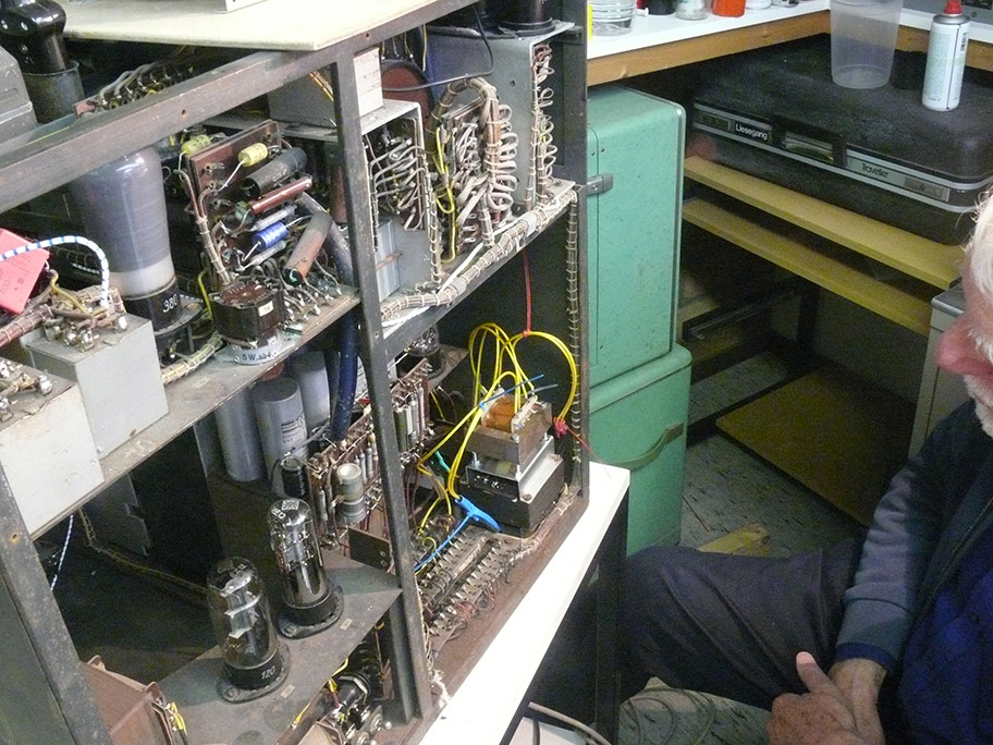
The new transformer mounting is fitting quite well upon the old faulty transformer
4.
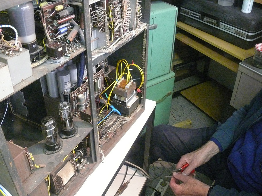
Following Antoon Steenbakkkers' advice:
testing the transformer device whether 'corona phenomena' are occurring.
We tested it between 2 kV up to 5 kV
Not the slightest signs of corona sparking could be detected.
5.
Hans Hans is using genuine high quality German wartime cable-wires
Once manufactured by the: Leonische Drahtwerke AG Neurnberg
This high quality wire is of an exceptional construction:
around the tinned copper wires core - we find first a quite heavy 'wound 'silk-wire layer' then another high quality insulation, yellow coloured insulation with 'fire-resisting properties' and a glass-like outer flexible skin.
6.
Our aim is, to keep the Console as much as possible in its genuine shape
Always bearing in mind: that the genuine status should be possibly restored.
7.
We are approaching the first tests, whether our setup is functioning as expected
Which it truly does!
8.

After we concluded it performs well, the transformer pedestal should be mounted definitely; using the existing (old) transformer screws
9.
The three different filament voltage wire groups representing are:
4 V = blue (outer winding-layer)
12,6 V = white (middle winding-layer)
6.3 V = red (inner winding-layer)
We even used the according coloured tyraps.
We kept the new wire a bit longer then seemingly necessary, our consideration was that during the mounting process we could conveniently place the transformer at the free RFG5 valve base, temporarily, of course. The about 80 years old wiring has become quite brittle, and it must be handled with quite some care.
10.
Viewing it slightly differently
11.
We are quite pleased, that our Nachtfee Console started functioning again
The A-Scoop crt is a true dual beam type, and it necessitate 4 V for its filaments; which is operated at, say, a - 2kV voltage level. Therefore great care was taken with its insulation against ground.
12.
The thin 'video' noise floors at the left and right-hand circular LB 2 crt is the noise floor of our IFF receiver without any input signal
I consider stage of affairs being quite a relieve for us!
13.

Getting an impression from the public perspective
14.
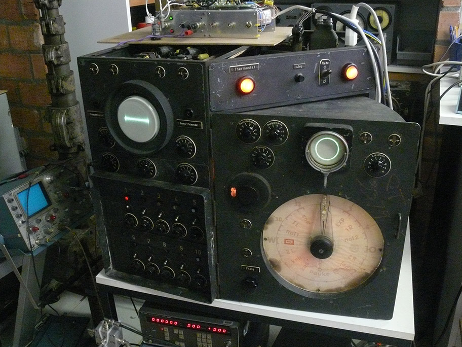
Last impression of our restored and again functioning Nachtfee Console
15.
Returning to
Chapter 9 of the Nachtfee acryl project
To be continued in due course
By Arthur O. Bauer
![]()