
Nachtfee-Aircraft-Display-Reconstruction
A new Survey
Among Rudolf Staritz's inheritance,
I discovered a circular deflection units fitted for a LB 12, circular cathode-ray-tube CRT.
More or less similar kind of display unit was built in the Nachtfee Console.
Page initiated 9 December 2021
Current status: 3 September 2022
Part 1
Part 2
Part 3 (29 December 2021)
Part 4 (7 January 2022)
Part 5 (28 January 2022)
Part 6 (7 February 2022)
Part 7 (18 February 2022)
Part 8 (18 March 2022)
Part 9 (25 March 2022)
Part 10 (1 April 2022)
Part 11 (1 April 2022)
Part 12 (21 April 2022)
Part 13 (29 April 2022)
Part 14 (3 June 2022)
Part 15 (17 June 2022)
Part 16 (18 July 2022)
LB 2 circular integrated within the accompanied deflection mounting
My first consideration was the application of a similar control-screen presentation within the Nachtfee main console.

Comparison between both presentation displays are quite apparent
The latter display had once been photographed on the Nachtfee console.
(one signal constituting the EGON signal which returned via the FuG 25a transponder and the second one representing the actual signal phase of the TB reference inside the simulated aircraft)
Which one represents the TB reference can only be determined - by operating the "Phase" control which only responds on "non-coherent" signals.
Please consider our YouTube film explaining this aspect Film 00086:
Considering that the entire Nachtfee Survey did start with: Radar News 19 (notice last page)

Let us bear in mind the: Adjustable Airborne Presentation Unit
Some of you will imagine what our future aims are.
Our aim this time is: - to try to imitate a display module which - more or less - is looking similarly, to what is drawn above.
We may consider, that the presentation presented within the Nachtfee Console, should equal the one employed within the Aircraft Display unit.
But, most likely - as this display originating from Rudi's collection, it will not originate from another Nachtfee console - but from a regular German airborne (short range) radar presentation.
This perception proved to be valid, as the Nachtfee LB 2 presentation operated with a deflection yoke of ca 1 H - whereas our new LB2 display deflection yoke had only a 50 mH inductance. We may consider that it once had operated at a rate of ca. 2900 Hz, whereas Nachtfee's PRF is 500 Hz.
Our first thought is: - why not letting it operate at a PRF of 3000 Hz (exactly 6 times 500 Hz).
Consequently: only once time within 6 periods (spot-rotation) the Nachtfee video signal-pulse will be present, thus reducing the displayed video density.
Optionally 2000 HZ would be an option too.
Which situation is most efficient is to be determined during this Survey.

This constitutes an example which we would like to employ more or less equally (The CRT used in this configuration differs a bit from our LB 2 type)
Ho is to be connected onto ground; and the two dual (left and right - up and down deflection-yokes are representing the: x an y axis)
Our first aim is: painting on the fluorescent screen - a first-order Lissajous between the space between the inner and outer cylinders on the CRT screen.
The essential pre-condition hereby are: that the deflection fields being rectangular to-one-another and that there exists a phase-difference angle of 90°.
90° can easily being accomplished by simple employing according ladder-network arrangements.
Our preliminary perception is: - to supply some sine-wave energy such the the exist between the two grouped coils there is maintained a phase difference of 90 degrees.
Dick Zijlmans was so kind to bring and supply us a Philips power amplifier of 15 W (max), constituting (stereo) 800 Ω and 8 /16 Ω. leaving to us enough deflection power for our proposed experiments.
Hans made a quite nice mechanical arrangement for our next experiments.

The schematic of the our deflection power amplifier; please notice - that all signals dealt with are sine-waves
A stereo amplifier.
The necessary deflection energy isn't yet known, as we definitely have to cope with non adequate deflection-yoke self-inductance;
and because all is in an experimental stage, it is very convenient to possess sufficient (variable) deflection energy.
We tend to suppose, after some 'back of an envelope' calculations, that 800 Ω might be a good choice.

Hans Goulooze built a sound experimental set-up
The gear-wheel allows deviating the true deflection axis; a provision for us not of significance.

Hans built a rather nice experimental testing board, albeit simply constructed of interconnecting wires
The power supply in the background will, Deo volente, supply our 1 to 2 kV HT. (as id once did in the first year of our Nachtfee starting experiments 2011 .. ca. 2012)

In front left-hand side one of the three 90° phase-shifting ladder networks (500 Hz - 1000 Hz and 3000 Hz)
We have investigated whether it would be possible to get access to the deflection yoke inside the tubular construction, which is, in our perception, far too dangerous; because
we have no substitute if something goes wrong.

Our current Philips amplifier; providing 8 Ω and 16 Ω as well as 800 Ω
After, the system is, Deo volente, operating satisfactory, we know the amount of energy is necessitated to operate our substitute display unit.
Thereafter we can provide simpler, and much more space efficient provisions.
Using a stereo amplifier is necessary - as we have to provide similar amounts of deflection energy for the x and y axis deflection-yokes.
One channel has, however, to provide more amplification, as it has to compensate for the signal-loss due to the phase-shifting ladder network.
(2) (16 December 2021)

Principle schematic as to get painted a first order circular Lissajous on the circular LB 2 CRT
Please notice, that X and Y being interchanged in the drawing above.
The amplifiers provide, at choice, 2 x 800 Ω (supposed sufficient) and also 2 x 8 or 16 Ω.
I have drawn one couple of deflection coils vertically and one set horizontally; but it isn't known which one actually have to be fed with the 90° phase-shift signal. As a incorrect connection will cause a counter move of the painted signal video.
Which latter will cause - that when the Nachtfee order signal will rotate opposite as is accomplished with the Nachtfee order pointer;
for example: when the order-pointing being rotated clock wise, the aircraft display will show an anti-clockwise rotation.
YouTube Film
Film 00093: Viewing the preliminary experimental set-up. The module on the left - in front, is a stereo amplifier; certainly too heavy in power. But is chosen as it should deliver every wanted energy level necessary as to get painted - the first order Lissajous figure - at the fluorescent screen of our LB 2 CRT. We 'inherited' from Rudolf Staritz's collection a LB 2 CRT inside its deflection Yoke. But, we measured ca. 50 mH for each of the the two (X - Y) sections. Whereas, the deflection Yoke sections measures ca. 1 H (Indicating that it originated from a German wartime aircraft radar set). The Nachtfee PRF is originally 500 Hz, but it is doubtful what amount of deflection energy is necessary as to cope with 50 mH Yoke inductances. When a 500 Hz sine wave signal is demanding a too high driving level, we could consider: 1000 - 2000 or 3000 Hz deflection frequency (the signal signal of 1000Hz will then only appear: every second time per spot rotation, or every fourth time (2000 Hz) or every sixth time (3000 Hz) per full rotation. The oscilloscope is directly measuring across the deflection coils fed via the channel with the 90° phase shifting ladder network. Albeit, that in this experiment we remain using the ladder configuration fit for 90° at 500 Hz only. Our aims, this time, being to watch the signal amplitude across one of the (50 mH) deflection Yokes (coils) (yet unknown is whether it actually concerns the X or Y axis).
(3) (29 December 2021)
Our aim these days being to paint a first order Lissajous circle.
This necessitate that one axis being fed with a sine wave call it constituting the X - axis and the Y - axis has to be fed with the cosine of the the signal which needs a 90° phase-shifting provision.
The X channel on the left-hand side and the Y-channel on the right-hand side
The painted ellipsoid on the screen is a bit over-exposed
Both using 1 : 10 probes.
It is quite clear that the 90° phase-shifting network isn't operating appropriately.
As to investigate at what signal frequency the ellipsoid axis is being painted horizontally or vertically - I changed the kind of signal source and used instead an analogue signal generator.

And at 1000 Hz the ellipsoid axis was parallel onto the Y-Axis
Remaining only adapting accordingly the X - axis amplitude.

This photo is showing that apparently our 90° phase-shifting network works appropriately at 1000 Hz

A test brief test was accomplished, whether the generator output impedance had an influence of the performance of our 90 degrees phase-shifting network
It didn't; the only effect noticed was the that over-all signal level changed but not the shape of the painted ellipsoid.
YouTube film
Film 00094: The experiment today is: investigating at which frequency an ellipsoid being painted exactly parallel onto the X or Y-axis. We normally are using a Philips/Fluke synthesiser at exactly 500 Hz. A circular Lissajous figure can be painted when the signal amplitudes in the X and Y channels are equal and there exists a phase-difference of 90°. Pre-condition we need sine-wave signals. As to make life more simple, I took an analogue tone-generator and manually started to go down or up with the generator frequency. It soon proved that going up with the generator frequency the ellipsoid-axis becoming more and more parallel onto the Y-axis of our oscilloscope. And just at 1000 Hz it was exactly parallel and the X-axis amplitude had only to be increased and a sound ellipsoid being displayed.
(4)
On Thursday 6 January 2022
Hans Goulooze and I have started to get the deflection energy right at the, not yet operational, test set-up.

Our first aim today was - to get the supplied voltage across the two deflection coils in line
The oscilloscope down on the trolley shows a more or less correct X - Y deflection pattern across the two deflection X and Y systems (coils). But the sine-wave deflection voltages being actually only ca. 2 volts effectively.
Consequently, what matters are the according deflection currents through the yokes.
But, first it was considered to make our display setup operational.

And, quite surprisingly, it functions rather well, instantly
Apparently, Hans Goulooze has really done a great job.
The tiny blip, about quarter to the our, is derived from the for quite a long time existing Nachtfee substitute interface; in use with the existing aircraft display substitute (since, say, 2013). Its appearance is entirely different from what we encounter at the LB2 display integrated in the Nachtfee console (Please, notice next photograph). However, our aim today is to get some kind of signal-display at our, preliminary, aircraft display reconstruction.
Let us, notice how similar LB 2 CRT performs within our Nachtfee Consol, in contrast to the shown performance above.

I suppose, that we might have to reconsider the circuit design later, as to provide a more or less similar display presentation as being used within the existing Nachtfee consol (shown here)
But, as to get a similar presentation our circuit has to be re-designed about the deflection cylinder.
However,
the tiny signal blip (shown at the second foregoing picture) originated from the since ca. 2013 existing - aircraft display substitute, (rather well operating) interface. Which is being fed from the used Philips/Fluke signal synthesiser and from the FuG 25a transponder.
It was also noticed - that the X -Y painted Lissajous is horizontally a bit out of centre (not well visible here).
Therefore, we chose to implement series resonance of the deflection yokes, first. This allowed us to inject, via a resistor, some dc current which variable value and polarity should move the entire Lissajous figure in the X and/or Y planes appropriately.
This provision works sufficiently good.
I suppose - it saturates the magnetic Yoke core(s) more or less.
And, is also allowing us to match favourably sufficient, onto the quite low impedance yoke system.

This simple circuit is showing our principal schematic; operating series resonance yokes allows us to operate the yoke coils optimally
For our current understanding, it doesn't really matter whether the cosine signal is fed onto the vertical- or the horizontal deflection coils.
In an original German aircraft set - they introduced a DC bias, but in our circumstance we have to deal with the output transformers used with the 800 Ω transformer winding; at one end connected onto ground.
Therefore we have introduced firstly a single series resistor in series with a variable voltage (current) source.
As to get an impression what the actual resonance frequency is - we disconnected the frequency synthesiser (500 Hz) and connected our variable signal source instead, and measured the ac voltages across the terminals a and b; where we get a clear indication of the point of maximal voltage across these noticed terminals.
We knew already, that the voltages across the deflection coils are ca. 2 V ac (sine wave).
Now the deflection currents becoming essential - as at series resonance, the ohmic circuit equivalent is mainly behaving as a real (low ohmic value) resistance (but the coil resistance is also limiting the Q-factor).
Secondly, it becomes possible to supply in one or both deflection coil sections a DC current in such a way that the painted Lissajous circle is moved within the given graphic CRT scale.
The variable voltage source in series with a resistor is only necessary to minimise the X or Y direction(s) out-off centre presentation (centre position).
In our case, it was only necessary to shift the X-plane centre (moving its X-plane towards right, a bit).
The only parameter that had to be adjusted was the amplitude of the painted Lissajous. Why?
Because, this type of circular CRT:

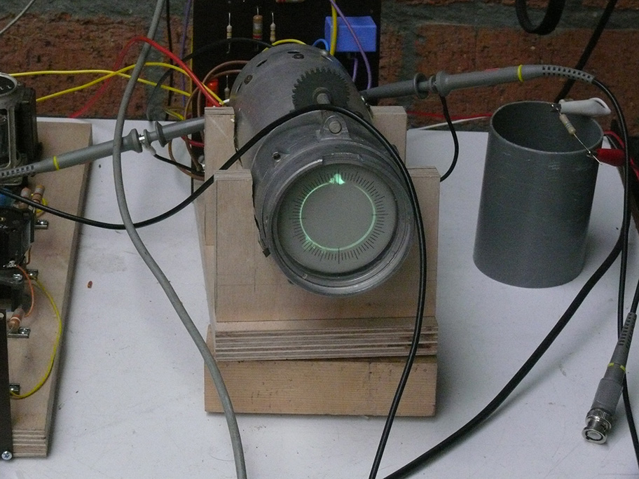
The conical cylinder constructions, are quite well visible
The (circular deflected) electronic beam has to pass just through the space in between the conical inner and outer cylinders.
Logically, when the deflection energy is too high or too low, the electronic beam will not be visible, consequently the electronic beam can't reach the phosphoric screen layer, as it is touching (or even beyond) one of two metal cylinders. Which might even do some harm - as the electronic beam spot can heat up the metal conical cylinder bodies.
In due course, I would like to explain these phenomena by means of an additional YouTube film.
In case of our experiments, the application of the Philips stereo amplifier, allows us, at will, to set for a wide range of deflection amplitudes (currents).
Thus, no screen display, first try to find the correct deflection currents necessary.

Down on the left-hand side, we notice the experimental 90° phase-shifting ladder network, as to create the necessary cosine signal path
Adjusted at 500 Hz.
The Lissajous connected across the two deflection yokes painted at the Tektronix oscilloscope, looks perfect, but the pained Lissajous on the CRT screen isn't 100% perfect. (please bear in mind, that the X - Y probes being attached across the deflection coils). Most likely, now it becomes a matter of fine tuning at resonance of one or both of the deflection yokes (all in series resonance)
We actually measured that the real resonance of the two yokes are some 50 Hz below 500 Hz. The problem is, that we have to deal with ca 2.2 µF (series) capacitors, and most commercial values are 1 µF or 2.2 µF. It might be worth to operate 2 x 1µF in parallel. Maybe this will minimize the resonance detuning (500 Hz).
Measuring resonance - can be best accomplished by using an analogue electronic voltmeter, and simply watching the points of true resonance (maximal scale pointer deflection), and thereafter comparing what the response at the display will be.
It proved necessary, to detune the phase-shifting ladder-network additionally as to get the over-all (painted Lissajous) performance optimally (maybe also due to some hysteresis).
We have also to bear in mind - that the deflection yokes are being influenced by the properties of the cursive parameters of the metal iron-yoke-cores.
Albeit, the the painted Lissajous at the Tektronix oscilloscope is seemingly perfect (the two probes being across the two yoke sections still) this will not say - that the painted Lissajous on the LB 2 CRT screen is optimally sound, yet.
Please bearin in mind the foregoing chapter, as both deflection yoke section being driven by a Philips stereo amplifier.
Next, we will deal with an experimental supplement.
(5) (26/28 January 2022)
Please bear in mind, that the foregoing experiments were accomplished with the Philips sound stereo amplifier.
Meanwhile, Hans Goulooze had constructed a kind of test board with 2 x EL84s and an ECC82 as a two channel pre-amplifier.
One for the direct 500 Hz signal (sine) and the second channel possessed a three sections ladder network for 90° signal phase-shift as to constitute the 'cosine channel'. Its purpose is to allow that on the LB2 circular display screen can be painted a first order Lissajous figure.

However, we encountered in the beginning on Wednesday (yesterday) quite some pit-holes, as the two output signals provided at the transformer output were highly distorted; and accordingly the painted Lissajous on the LB2 CRT screen
We encountered all sort of nuisances:
The chosen concept being: each channel possessing: two power stages with EL84 valves in class A.
Consequently, among the short-comings of the output transformers - the dc anode current is also saturating the transformer cores to some extent.

Our current signal source is our tone generator, as coherence, in this stage of experiments, did not yet dare; but we had the advantage that we could measure over a quite broad frequency spectrum

As to eliminate the dc current flowing through the anode coil-windings of the output transformers;
we introduced an anode resistor (ca 5 kΩ) and connected in stead the primary coil-winding via a suitable capacitor.
This diminished some of the distortions, but also limited the actual value of the signal outputs

Our next move was to operate the EL 84 valves instead of pentodes wired now as triodes
This introduces a second order distortion, but eliminates the according third order distortion.
Please click at this photograph as to get it in magnified pdf
It is quite evidence, that the circle painted at our X-Y oscilloscope (down more left-down) and the one painted at the screen of the LB2 crt differs quite much.
The only difference is: that the LB2 yokes being now, more or less, brought in resonance (500 Hz) and the X-Y channels are (still) being measured across the deflection coil systems. Apparently the voltage across these coils differ considerably from the signal form of the caused magnetic deflection flux.
In my understanding, in our case the Q-factor of the tuned deflection yokes are "smoothing" the sound sine-wave signal from yoke-coil-current distortion.
There hardly will exist a more sound evidence of the considerable influence of the soundness of the sine-wave curves; be it concerning sine- or cosine- waves signals.
I suppose, that improvements must be first achieved by optimally tuning at 500 hertz of both deflection yoke currents.
Next:
Leaving the EL 84s wired as triodes, but now again started with introducing the Yoke coils to operate in series resonance
The advantage, is, neglecting the ohmic resistance of the yoke coils and maybe the according B-H parameters of the yoke cores, that we get rid the 'inductive' system loads;
as we know - that a tuned series resonance L/C configuration acts as an ohmic load.
I had already started such experiments before, and had found out that one of the yoke-coils with a 2.2 µF series capacitor resonated at about 515 Hz. A bit to high and by adding parallel some available (suitable) capacitors in parallel, we could lower the resonance frequency to within 2 Hz of 500 Hz.
Let us, reconsider again, its principle schematic
Remember: the Ls and Cs constitute series resonance tuned circuits at 500 Hz. The two parallel coils being considered as a single (axis X or Y) coils arrangement. There is - no way around as there does not exist a possible means to approach each coli (inductance) separately.
V is to be measured across the connector terminals 'a' and 'b' separately.
Albeit expected, we encountered a curious phenomenon:
again: click at the photograph as to open it in more high resolution pdf
The X-Y scope channels being connected across the two yoke-coils showing quite some distortion; visible as the painted circle is from perfect
But, the painted circle on the circular deflection screen did not show now similar amounts of distortions.
Notice, that maybe, one of the yoke coils might have to be tuned better; as resonance at about 500 Hz; which wasn't so clear as the other channel possesses.

Comparing the circular LB 2 CRT screen with the foregoing photo, more in detail, it is evident that the painted circular trace is far better than shown on the X-Y scope.
Introducing series capacitors have the advantage that it becomes now possible, that we can let flow two dc-currents through the two sets of yoke coils; doing so it is possible to move the painted circle in the X and/or Y plane, as to centre the paint circle optimally.
Will be discussed in due course later, again.

Measuring the resonance frequency of the cosine yoke coils resonance
Resonance was determined by measuring the resonance -peak voltage across the cosine yoke coils.

We had to provide 8.9 V through a resistor of 3 kΩ, = approx ca. 3 mA.
Not really a great amount of position-shifting current,
However, I cannot judge whether this is due to the permeability of the the iron yoke cores.
This aspect was dealt with in the genuine FuG 202 schematic:
What next?
We would like now to pull-out the two EL84 valves, and wire instead a pair of LV 1 valves. The only slight change is, that the LV 1 valves need 12 V filament voltage instead of 6 V;
and, operate them also as triodes first.
Leaving the test board further as it is currently.
The blue quite heavily sized capacitors of 2.2µF could be replaced but I believe that their quality is quite superior.
The pink wire down on the right-hand-side constitutes the 'cosine signal' line; the yellow cable conveying the 'sine wave' signal.
What should be documented, essentially, is the behaviour of the two (sine and cosine channels) in case the series resonance being bridged by short circuiting the series capacitors.
TO DO: taking photographs of both situations - direct connect onto the transformers and with series capacitors the yokes operating in series resonance modes
One cannot imagine what then will happen. Huge distortions in the painted circular first order Lissajous figure.
The series resonance filtering is causing smoothing of the presented sine-waves.
Distortion of the painted first order Lissajous, originate, in our case, from harmonics in the currents fed onto the two yoke X-Y deflection systems.
Whereby, apparently, the imperfective of the sine wave and the according cosine wave - is causing the improper painting of a first order Lissajous figure.
Un-expected, however, is that these downsides can be, to some extent, be neutralized by assuring the degree of distortion of the currents flowing through the two deflection yokes.
A point of due concern, is, to investigate the behaviour of the purity sine-wave wife current through the sine-wave signal channel through its according deflection Yoke.
(6) (7 February 2022) (accomplished, however, on Thursday 3 February 2022)
We continued, as already noticed, with replacing electrically the 2 x EL84 valves by a pair of LV 1s. A very nice valve, wartime, type with an 'S' = 9.5 mA/V and an anode dissipation of 10 W en very well fit for broadband applications. Albeit the latter isn't explicitly necessary for our application; as the PRF is 500 Hz only.
An advantage, these valve types were widely used in German wartime airborne radars, especially in video- and also in deflection applications.

Hans started to pull-out the pair of EL 84 valves and wiring instead the 2 x LV 1s
Leaving the rest unchanged, thus - using the same components, which proved to operate rather smoothly.
Later Hans Goulooze will, Deo volente, built it into a new frame, but for this stage of experiments it is sufficient.

Both LV 1 valves being wired and also operated as triodes (g2 + g3 + anode, all being interconnected)

Viewing it a bit differently, all connected components being still operated
The black transformer on the left-hand side- constitute the cosine signal channel (output); driving the according yoke coils.

Please consider in the quasi forth quadrant - the quite flatted Lissajous figure
which is hardly recognisable at the circular display (LB 2) in the rear; due to the fact that its X and Y yokes being series resonance tuned at 500 Hz.
YouTube Films
Film 00096: At the end of today, having modified the test circuitry, where we have removed the two EL84 valves and have replaced each EL84 valve electrically by a German wartime valve type LV 1; but the circuitry remains unchanged. And it straight away operated rather well; albeit that the two LV 1s obeyed to different sensitivity (un-selected wartime productions). We replaced the lower sensitive one, and since it works rather fine. The only matter we had to change slightly, was that the 90° phase-shifted 'cosine' signal necessitated some readjustment of its signal phase, and we therefore implemented a small tuneable potentiometer. As a 90° signal difference is essential for painting a proper first order Lissajous. What is causing some troubles are the harmonics of the 500 Hz sine wave. Therefore, it is very convenient that we can tune the deflection circuitry at series resonance (500 Hz). What we cannot control is the B-H performance of the deflection yokes inside the CRT housing. All is operating in the current mode, as it is the actual current that induces the two according magnetic (X-Y) plains. The advantage of operating series resonance, is, that we can simply add some provisions to move the painted figure in the X and Y planes at will (up/down at will) as to centre the circle inside the the CRT screen. The series capacitors are blocking the dc components from entering the transformer output coils. The DC bias are quite low and of a few mA only.
Maybe worth noticing, is, that we don't use a form of feed-back, which would reduce signal distortion considerably. The only kind of feed back we use, is, that the two final valve stages (sine and cosine) are using a semi-feed-back. The according LV 1 cathode resistors being divided by two similar value resistors of which one being bridged by a sufficient electrolytic capacitor; so that the there remains a form of half-way of feedback. Our main aims are simplicity and the application of components at hand (or purchasable). The main reason for this - lays in the fact that feedback is also causing a form of phase changing, which we would like to prevent in combination to our sine- and cosine-channels. On the other hand, both signal are of equal value, and thus causing equal phase-shifts.
(7) (18 February 2022)
Today, Thursday 17 February 2022, Hans brought-in his improved test setup.

He replaced the ECC82 by a wartime valve EDD 11 (dual triode) and added an EF 14 (high slope valve) as a 'video signal amplifier' as to allow the Nachtfee signals being appropriately displayed
In this setting he operate yet both 'Steel Valves' at 6 V filament, whereas, later, both valves should be operate at 12 V dc; by means of the two filaments in series.
Our aims are generally: to try to operate valves which existed already in those wartime days.
Secondly, operating circuitries, which could have been known in these days.

At least, we can display both two essential signals on the Nachtfee display reconstruction
The larger signal at, say '20 passed the hour' constitutes the Time-base reference signal (TB) which signals the actual 0° (degree) of the time-base generated in the aircraft display system. In our setup, the TB pulse being derived from an external synthesiser, whereas the current time-base being generated from an older type (less drift free) Philips synthesiser (albeit both carrying the same type number, but possessing a slightly different concept), versus the modern Philips synthesiser (also of the same type-number but carrying a different extension designation).
This time-base reference: by means it is possible on the stationary Nachtfee Consol to adjust properly the signal phase setting; which is telling the actual phase difference between the ground system and that in the moving aircraft.

Another view on the same situation
The smaller (thinner) signal at about 'half-an-hour' is the actual Nachtfee ground signal, which should indicate what the actual Command or 'Order' should be next accomplished.
What has to be accomplished first is to eliminate the displayed signals pointing to the centre of the time-base-circle.

For it we use a "Schottky" diode - as to eliminate these negative pulses
The diode is visible down on the left-hand of this photograph. Its actual size is far too big, but this sample which we had instantly at hand.

As to let this test setup function in conjunction with our Nachtfee system, we again have started to operate the Philips Synthesiser in the background
I experienced already for a bout a decade, that this older type (in the background) drifts a bit against the one used in conjunction with the already existing aircraft display reconstruction, where a HP oscilloscope being operate in X-Y mode and is painting a first-order Lissajous.
But which isn't capable to display signals as we are looking at currently; and which are, more in the line of what is displayed at Nachtfee consol.
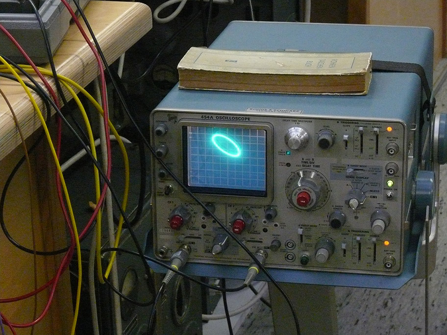
Viewing a Nachtfee console presentation

Please notice the signal at, say, 12 o'clock representing the actual Nachtfee order signal (received on the ground system again) and the the signal at 8 minutes passed the hours - which is the correctly adjusted aircraft time-base-reference pulse versus the actual time-base signal generated inside the Nachtfee Consol. In our case now being derived from a Rb-atomic standard.
When adjust as shown here, it is ascertained that whatever the actual aircraft time-base-phase is, that every Nachtfee Commando or 'Order' will be displayed correctly (in the time-domain/phase-domain).
The Nachtfee Consol control screen on the ground and in the aircraft both being of the type LB 2.

A photograph of our current (yet regular) operated HP X-Y oscilloscope display
I suppose the presentation difference is quite evident.
After we 'inherited' Rudi Staritz's LB 2 including its deflection yoke - that the idea engendered as to adopt it technically.
How do we know what actually had been once used in early 1944?
These drawings constituted the nucleus of our entire Nachtfee Survey
Essential, are both the consol drawn down left of the Freya-EGON apparatus and the display designated "Adjustable Airborne Presentation".
With some imagination our test setup where we started this reconstruction with, shown next:
With some imagination you might follow our concept philosophy (still in its infant state)
Of course, this setup is first to get it operational.

Later, Deo volente, a new frame has to be build where what is contained at the electronic circuitry should be mounted underneath such kind of frame
For example, the two (white) upper controls in the background - should later be accessible both down at the ultimate front-panel.
YouTube Film
Film 00097: Hans Goulooze has modified the test frame (board) with two wartime German valves EDD 11 (in front) and an EF 14, which functions as a 'video amplifier'. The two LV 1s have already previously been dealt with. The signal-pulse is showing the Time Reference pulse (TB) which is an essential parameter in the Nachtfee system. It is evident, that one should know exactly what the current time-base phase (0°) is, of the aircraft system is.
(8) (18 March 2022)
Today we have decided that we should mount the experimental rig on a movable table, as by this means we easily can arrange the replacement of our since 10 years existing substitute aircraft reconstruction.

This photo shows us, what we are intending; albeit not yet being wired
Hans first will modify the wooden test plate with some additional panels
Also a substitute to WK 25a, which consists, in our case, of a 50 Ω resistor possessing a centre tap.
This is creates a virtual 'ground' (MBB) centre connected.
The German aircraft electronics operates with +BB and -BB each connected onto respectively the 'plus' and 'minus' of 24 / 26 V battery terminals.
The LV 1 valve filaments (12.6 V) being now interconnected in series as to operate at 25 ..26 V dc. The centre-tapped 50 Ω resistor guarantees that when more valves being arranged that when a valve being pulled-out the series circuit, will not face too much voltage/current overloading.
For this occasion, we first would like to add mounted vertically this 50 Ω resistor.
As well as some additional controls and BNC connectors.

Viewing it from a different perspective
The provision of the power supplies being mounted underneath.
YouTube Films These films have been recorded shortly before, and showing the achieved improvements last Friday 11 March 2022.
I have to apologise that I announced that the recording date being 16th March whereas it concerns the 17th of March.
Film 00098: We struggled for some weeks with very curious difficulties; which, as so often, originates from defects (faults) in several modules at once. It takes often some weeks before, Deo volente, all inter-actions being determined (also with some luck). We are viewing at the LB2 screen, kept with a genuine magnetic Yoke arrangement. We notice the steady signal originating from the instant that the time-base synthesiser is passing 0° (degrees). This reference is essential for operation of the entire Nachtfee concept; as distance is also changing the instant of the video-order signal arriving at the aircraft display screen. For it, the TB reference pulse passing just through 0° is telling the Nachtfee Consol operators what the actual phase difference (λ f = c) (distance) is (360° covers a distance of 600 km; in radar term 300 km - as distance has to be bridged twice. From the Nachtfee consol towards the aircraft platform and reverse). On the ground the dedicated Consol operator knows how to adjust the phase-setting. We know when this is done correctly, the Order vector arrives exactly just on time at the Aircraft Order CRT screen. This pre-adjustment has not been accomplished here.
Film 00099: We are viewing now at the LB 2 CRT in the Nachtfee Consol. The bright pulse up constitute the Nachtfee aircraft TB (time-base) reference. The weaker pulse at 180 degrees is the genuine Nachtfee Order signal, now operating the FREYA-Polwender switch; which rotates exactly 180 degrees (The two sine-wave output wires being interchanged. In a coherent system, which Nachtfee is, rotated the (Order) signal for 180°. The Phase control changes the entire system-phase. But Nachtfee constitutes a coherent system, and this control will not visibly cause any change of a signal vector; but it does change the signal phase transmitted towards the aircraft. By operating the 'Phase Control setting' it will cause the instant of the signal arriving at the aircraft display. As to adjust correctly one need to know about the TB instant of the aircraft TB at 0°.
Film 00100: Visible is a good example of the Phase-control inside the Nachtfee; which as explained previously determines the instant of the Order signal at aircraft display. The 0° (TB) reference is allowing to predict the instant of the arrival at the aircraft display in the aircraft.
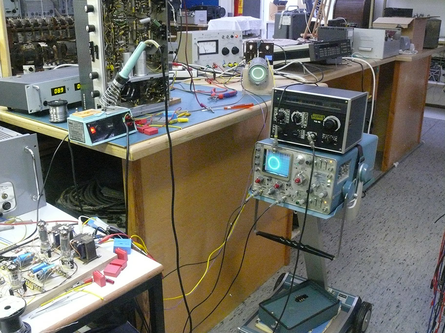
(9) (25 March 2022)
Building the new, experimental, aircraft-display configuration and according supplying systems, on a moveable table

The future display still set-up experimentally
We face now, especially, difficulties in respect to shape of the video and the time-reference pulses.

Our main difficulty is to display the steady TB reference pulse, which signals towards the Nachtfee Consol on the ground, what the actual 0° phase in the aircraft after reaching the ground system is
This reference pulse is essential, as by the means of this signal the Nachtfee operator can determine the correct phase-setting on the ground; as to secure that the instant of signal-arrival coincides with the the actual Nachtfee Order signal as well as what is displayed on the aircraft display screen (LB 2)
Video signals constitute a quite high frequency spectrum.
In an aircraft they used from environment screened tubular (square) systems as to view the weaker video signals.
It might even have been enhanced by a particular lighting-up circuit.
Please notice the grey tube on the right-hand corner of the table; which should be fixed as to screen-off surrounding light.
The circuitry on the "board" should be later be mounted "horizontally" under the LB 2 CRT Yoke unit.
What we already discovered that the instant of the 0° TB reference signal arriving at the screen of the Nachtfee Consol, arrives, when appropriate aligned appropriate no longer at say "eight minutes after the hour" but now about at 0°. Thus North and TB being likely received instantly. (as was the case in our foregoing Nachtfee console experiments)

The main video pulse is visible at, say, 14 minutes past the hour

It is quite visible that the main signals go together with some "trabant" pulses which should be reduced or, when possible be removed
This will demand modifications of the two interfaces until now being implemented in our system.
Finally:

The grey tube in front, constitutes our visual screening-off provision - as to get rid of unwanted surrounding light
This set-up constitutes only a temporary provision.
Though, it constitutes a necessary step in our empiric development.
Our ultimate aim is: to replace the foregoing display with the the already 10 years existing HP oscilloscope substitute (above) by the foregoing showed circular-deflected LB 2 display-Yoke system
The technical problems being well showed about the "north region" of the CR tube.
We have already made progress, but have to focus now to optimalise our long-time existing (> then a decade) two interface units; which had been fed onto the foregoing display.
Why all this?
Because previously we did not possess a genuine display substitute; which we since Rudolf Staritz death possess.
(10) (1 April 2022)
Yesterday 31 March 2022
We have continued our experiments with adding a circuitry which enables us to "high-light" the displayed video signals, like a strobe.
Because foregoing we noticed that the actual video signal weren't easily to be read at day-light.
An example of our last week experiments
But the Liechtenstein FuG 202 had already been fit with a circular CRT type LB2
Before showing the experimental circuitry added today, I would like to show you first a quite reasonable CRT presentation resulting of our experiments:

Please compare this photo with the foregoing picture taken last week (here the video signal displayed at, say, thirty 37 or 38 minutes; whereas the foregoing was showing a video signal at 14 minutes passed the hour) at comparable daylight conditions
It is evident that quite some progress has been achieved.
Where both pulses at ca. 0 hour representing the TB (time-base) reference pulse, which has to be conveyed onto the virtual ground controlling EGON; which supplied also the signals onto the Nachtfee Consol. The TB pulse reference is constituting the aircraft time-base status at a certain instant just before it is being supplied onto the FuG 25a transponder.

We started with an experimental additional "Hell-Tast" circuitry
Which more or less being fed from and towards the video signal pin 9 at the test-plug at the FuG 25a. (Thus similarly used for transmission as well as reception)
We chose an additional video amplifier channel as to allow signal-level control for displaying the actual video signal as well as for the (Hell-Tast) strobe signal.
The advantage of operating two LV 1s is that the filaments can be arranged in series, and allowing the common 24 V (25-26 V) aircraft battery supply.
The EDD 11 will, Deo volente, be replaced by two RV 12P2000s valves (wired both as being a triode); each one driving the "Sine and Cosine" signal channels. The Cosine chain necessitates additional gain as the 90° phase-shifting ladder network is demanding an according rising of signal level; as to gain equal driving voltages of the two LV 1s power stages.

We (Hans Goulooze and me) were rather astonished by the fact, that the video signals being high-lighted but that also the first-order Lissajous has (virtually) disappeared
The level of suppression or cancelling being determined by the amplification factor of the "Hell-Tast" circuitry.
Not well visible is, that the rotation of the beam being anti-clockwise. And that then the first ramp is the slope of the actual video signal.

I suppose, for the time being, this might be a good compromise, which constitutes a nice, and practical, adjustment
Albeit, that this presentation might also be favourably

We have also changed, in the meantime, the Nachtfee Order or Command, vector

The signals fed straight-away onto the crt LB2 g1
The on the most right-hand side pulse is the 'TB' reference video signal originating from the virtual aircraft time-base; which should be equally on the LB 2 crt on the Nachtfee-Consol at 0°.
The video pulse left from it constitutes the Nachtfee Order or Command signal; originating from the Nachtfee ground station and being picked-up at pin 9 of the FuG 25a test-connector.
The "Hell-Tastung" (brightness increase) may saturate the painted video signal a bit, but is still sufficient as to indicate the actual Nachtfee Order or Command vector.
YouTube Films
Film 00102: Demonstrating our today's (31st March 2022) experiments, aiming to high-light the received video signals; as to distinguish between the regularly painted first order Lissajous and the received video signals. Viewing what is displayed at our modified crt presentation. The first screen shown is rather an improvement and the video signals being very much better pained than ever before in our foregoing experiments.
Film 00103: Starting again showing the experimental set-up of the additional video amplifier, which function this time is to high-light the video signal pulse against the regularly painted first order Lissajous figure. The first experiments showed us, that the amplitude of the additional video amplifier steering the reduction of the negative grid 1 (g1) of the LB 2 crt display (decreasing its negative bias, will cause a brightening-up of the painted crt trace. It showed, that unexpectedly the reduction of the video amplitude is high-lightening the painted first order Lissajous and video signal reduction is causing a reduction of the painted non-video signal contends; such as is the painted first order Lissajous.
Film 00104: Hans Goulooze shows us what occurs when he increase the video signal fed onto the first grid (g1) of the LB 2 crt tube. With increasing video content supplied onto the LB 2 g1 grid, is cause a steady reduction of the painted first order Lissajous on the crt screen; remaining the still high-lightened video signals.
Film 00105: To close finally today - We suspected that, maybe, the coupling capacitor between the LV 1 anode circuitry and the g1 of the LB 2 crt, might also showing some influence (100 nF versus a 4700 pF) (investigating whether the 'time-constant' is part of its behaviour); which, after all, did not was the case. Finally, quite unique, in my perception, is watching the signals at the LB 2 crt screen and the accompanied signals shown at the oscilloscope screen. I suppose - that hardly one of you have seen this, simultaneously, before.

After reconsidering during my wake-up this morning - I came to the following hypothesis: the crux of the the capacitor '61' which, in my current perception, is being extra charged with an increasing negative voltage by the increasing crt beam-current of the LB 2 crt. The beam-current is also increasing the voltage across the luminance potentiometer '89'; which opposite ground - is directly connected onto - 2 kV.
Please consider now the foregoing screen-shot of the oscilloscope. Where we deal with pulses up to ca. 70 Vpeak (herewith decreasing the negative g1 voltage and herewith increasing the intensity of the painted signal at the crt screen).
These signals being fed onto the LB 2 g1 and in the first place causing high-lighting of the video signals; and herewith increasing the beam current. Consequently the voltage over the "Helligkeit" (brightness) and is also increasing the negative voltage across 'C 67'. The beam spot rotates exactly in 2 ms thus a video signal or signals will appear in shorter intervals. The RC combinations 'C 63/R 95' and 'C61/R92' are the to be considered R/C combinations.
The combinations 'C 63 and R95' have been considered as we experimentally reduced "C 93 twenty times" without any visible result.
Therefore: - the only time-constant determining network remaining is: "C 61 and R 92".
Thus: C 63 being fed with the Hell-Tast or the to be high-lighted video signal; which is decreasing the negative grid 1 steering of the LB 2 crt.
C 61 is due to the positive amplitude of the signal (ca. 70 Vpp) increasing the negative charge of C 61, and therefore suppressing painting the painted crt signal during at least 2 ms; herewith making temporarily the to be painted signal invisible; as long a signal is not additionally being high-lighted.
Capacitor 64 is regularly being fed by the regular video signal.
(11)
On 14 April 2022
Hans Goulooze did build a bigger test board for creating additional space valves the 2 + 2 extra valves: 2 x LV 1 and 2 x RV12P2000; to allow also full 24 - 26 V filament operation.

Hans' new test-board starts operating again
The 2 LV 1s as well as the replacement of the EDD 11 for a pair of RV12P2000s; its main aim was to allow by quite simple means to operate the entire filament circuit from a ca. 25 à 26 V dc supply. Because it since fits better in the reconstruction of the simulated aircraft display including its driving circuitry.

Viewing it more in details
The pertinax board with the potentiometers has to be replaced by an extended board allowing an additional potentiometer as well as another type of connections.

We encountered the nuisance that the scale of brightness of the LB 2 crt, was also influencing the deflection-sensitivity
This was caused by the Ri of the operated high-tension power-supply of 2 kV. Its output voltage being too much dependant of the crt beam-current.
We therefore we experimentally tried to investigate whether it is possible to by=pass the ca. 2 kV supply with an additional resistor.
The power-supply gives an output current of 3 mA, whereas we have to count with µAs beam-current.
To some extend this seemingly does work more or less well with a load of ca. 2,8 MΩ.

It is most likely that the HT voltage regulation takes place in the mains circuitry; by means of wire-wound potentiometers, as so often by British products
The general disadvantage is - that the output voltage (in our case 2 kV) becomes quite dependable on the load-current.
We later replaced it by two 5.6 MΩ in parallel

We also encountered a problem in the the brightness circuit of the display unit (left-hand potentiometer with the white shaft)
Probes being connected across the deflection yoke directly.

The two bleeder resistors (across the 2 kV) being kept a bit isolated during our current experiments
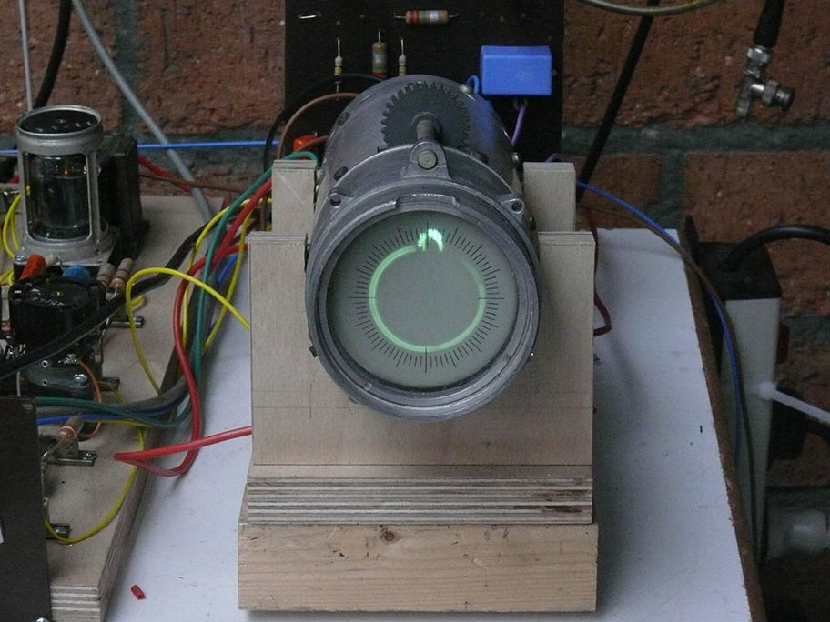
The pulse at 'North' constitutes the TB pulse constituting the 0° time-base reference signal necessitated on the ground as to adjust the Nachtfee-console 'Phase' adjustment correctly.
(12)
On 21 April 2022

Today Hans Goulooze did change the lay-out of the front-panel of our newly constructed test-board
One of our aims additionally was, to stabilise the 2 kV supply, which due to its construction, uses a wire-wound potentiometer in series with the 230 V mains line, as to allow a variable output voltage between say a few hundred volts an ca. 6 kV.
Allowing to this construction, the output voltage varies quite with the system load. In our case being ca. 800 µA (0.8 mA).
For it we experimentally wired 10 zener diodes type BZX 200 in series. In series with the HT line we added in series a 1 MΩ resistor and increased accordingly the HT voltage. It proved, however, that these zener-diodes conduct already at ca. 175 à 180 V.
We therefore will add one or two additionally in series.
The 1 MΩ (2 W type) series resistor, easily can cope with the current load, as its temperature stabilised at ca. 29° C body temperature.

This versatile PM 2401 electronic meter possesses a 10 x input voltage provision, with allows us to measure directly up to 3 kV
The additional advantage is, that the current load on the circuitry is also reducing.

It is evident that all is quite experimental as between the white and red connection we measure ca. 1750 V
The signal shown at the crt is the high-lighting signal, consisting of the TB reference and the the Nachtfee "Command Order" (shown on the crt at, say, 20 minutes passed the hour)

This PM 2401 instrument indicates a HT supply of, say, 1.8 kV
The high-light signal showing the two signals whereas the first order Lissajous (circle) being suppressed due to the R/C circuitry in the brightness circuit
YouTube film
Film 00107: Hans Goulooze has now modified the experimental board; today he replaced also the left-hand side of the control-panel. As to stabilise the ca. 2 kV supplied on to the crt circuitry, we added 10 BZX 200 zener diodes in series. Therefore we added in series with the HT line a 1 MΩ resistor; of course therefore the HT power supply had to be set at an increased output voltage. For two reasons, as to limit the zener current as well as to use the voltage swing across the 1MΩ series resistor.
(13)
On 28 April 2022

Today we made quite some progress
First we build-in the arrangement of 10 200 V zener-diodes, as to stabilise our 2 kV HT power supply; for it we need, of course, now about 3 kV with measured provides a current load of ca. 1 mA (1000 µA) all together (crt and controls consumption about 800 µA and the rest goes through the 10 x BZX 85/200 zener-diodes).

The 10 zeners being mounted on a plate with two rows of soldering contacts
For it we use the free space under the tubular crt-screen.
HT measurement being made by the versatile Philips PM 2401 electronic voltmeter, using the 10 x provision minimising the on the 2 kV circuitry.

We notice that we measure just over 2 kV HT supplied onto the display circuitry
The'"high-lightening" (Helltast) circuitry is operating, which we can see, as the circular beam-trace containing less brightness than do the TB pulse pointing north and the Nachtfee Order signal visible at say 5 minutes past the half-hour. This signal originates from the Nachtfee Order Console.

The Electronic Multimeter scale and 10x provision is well visible, which extends the maximal scale voltage being 300 V to 3 kV now, including an increase of the the Ri of circuitry.
Please notice that this instrument allows even current measurements up to a full scale of 1 µA!

We have changed the 24 V dc supply wiring, so that we rely now on the already available aircraft 24 (25 V) power supply (shown the new air-display board including the existing FuG 25a current consumption)

The free space on the top left-hand side should carry a stabilised ca 250 .. 280 V power supply
(14) (3 June 2022)
Beyond many projects, I suppose that we have reached a substantial point; leaving beside the progress made on the on-board stabilised power-supply.
We are using for "clamping" Schottky diodes, with their downsides of some value of leaking currents.
Why we haven't considered it previously I cannot answer, maybe we had a too high expectation of the performance of these, modern components.
But vacuum valves are constituting, at the low frequency spectrum, a merrily ideally performing diodes.
We therefore, maybe a bit late, decided to implement two RV12P2000s valves to be employed as "clamping" devices just where we have to eliminate negative pulses.
The two RV12P2000s can easily be fed (in series) from the available 25 V FuG 25a supply voltage.

Our first steps being always - to build it in a free wire arrangement, as to get an idea how matters are performing

The negative pulses should be eliminated - as its down-side appearance is visible in the next photo
We see that the negative pulses constitute ca. 50 V.

It is quite evident that the (ca. 50 V) negative pulse does not give information and should be eliminated

It is evident that the main content of the negative pulse is eliminated by means of clamping

It is clear that indeed the negative pulse has been eliminated
But does the "Helltastung" (think of a strobe like presentation) is functioning rather well
By increasing the "Helltastung" level - the entire painted circle will disappear - remaining is the brightened north pulse (strobe) solely.
(15) (17 June 2022)

Hans Goulooze once decided that the stabilised power-supply should be adopted onto the main circuit board; but not build on a wooden plate directly - but on an Al cover at a particular wooden sub-base

Some of you might have got the impression that our Nachtfee-aircraft reconstruction has reached a kind of hold
But Hans meticulously prepares matters in advance.
Fore it we went, yesterday morning 16th June, first to our the MLK premises, where we possess a well equipped workshop.

After due consideration, we decided to making use of more modern valve types, as the transformer at hand we possess only two 6.3 V filament windings, in contrast to the German wartime 12.6 V (GAF) types
Why?
Because the series regulator valve (notice it in the background) supplies at its cathode ca. 275 V HT; far beyond the break-down point between its filament and the cathode insulation.

Viewing Hans' engagement from a slightly different perspective
(16) (18 July 2022)

Hans Goulooze nevertheless was, albeit that the current summer temperature reaching >> 30° C, able to mount and wire quite some of the stabilised power-supply

Hans is using currently components of the 1960s, thus not yet wartime, but nearer to the wartime days, as we are now >75 years past

The compactness of the construction demands carefully testing

The valves are of post-war types (6.3 V), as wartime types would demand various alterations; such as having to use 12 V filament supply - which consequently would demand a different transformer type
Our project relying quite often on components on stock or in our possession.
Continuing with Chapter 18 on the next webpage
By Arthur O. Bauer
![]()