
Nachtfee acrylic substitute aircraft display
a new endeavour
Page initiated
on 5 June 2023
Current status: 10 November 2023
Part 2
Part 3
Part 4
Part 5
Part 6 Parts 7 and 8 can be accessed by clicking at them.
Part 9
Part 10 (since 20 October 2023)
Part 11! (since 27 October 2023)
Part 12! (since 3 November 2023)
Part 13 (since 10 November 2023)
This project runs already since September 2021.
We inherited a circular cathode ray yoke concept, which is especially built for the German Air Force (Luftwaffe) type LB 2
I first took a brief series of photos, maybe not in an optimal setting, but I prefer to consider it as a kind of tantaliser.
Viewing it as our device did arrive
1.

Viewing it from its right-hand side
2.
Please bear in mind, this is only a concept of combining our foregoing experimental construction and what it once might have, more or less, looked a like

Maybe you now understand that some similarity exists between photo 2 and the above wartime drawing
Most likely drawn by a capture German PoW.
It took us quite some time before we got a substitute aircraft display operating.
https://www.cdvandt.org/nachtfee-airdisplay-right-hand-side-new.htm

Viewing the acryl display substitute from a different perspective
3.

Our next endeavour should, of course, be mounting the components
4.
This will, Deo volente, being accomplished on an acryl, more or less, square base-plate; however, the screw-holes should be accomplished by an expert, as acryl is sometimes a tricky material in respect to drill holes.

Viewing it differently as to allow a more complete impression
5.

The darker sections at the phosphoric screen must originate from some reflections; as these aren't shown on the forgoing photograph
6.

It truly has become an elaborate acryl construction
7.
The tooth-wheel accessible on the top provides the possibility to adjust the the North signal (timing 0° marker) yoke - against the North line engraved on the LB2 crt display correctly

What a magic impression isn't it?
8.

The two holes allow us to access the 2 RV12P2000 valves in this context both acting a video-clamping diodes which after all perform better than semi-conductor does
9.

Marvellous, in my perception
10.
The two circular holes are for keeping the RV12P2000 base-sockets

This connector was a quite standard GAF connector, designed by Tuchel, which company became in the 1950s Amphenol (also known as List-Stecker)
11.
In the 1960s and 70s maybe 80s Amphenol edge-connectors employed in combination with flat-cable constituted versatile- and a reliable product;
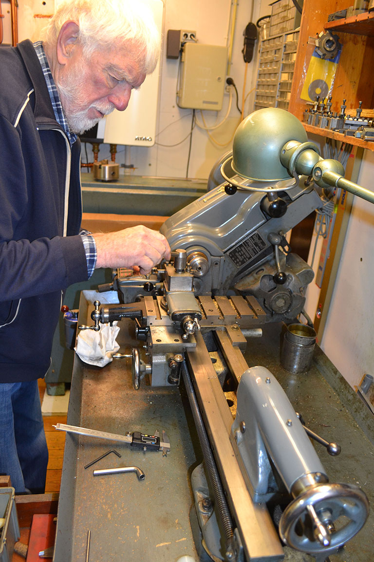
but its basic concept was German. It was after the war widely copied in France as well as Russia.
In 1999 we visited Vietnam and were walking in the streets of Saigon. Someone set down and was dismantling an electrical unit and I saw some components quite familiar to me. It proved to be a "Chinese" copy, but Russian made of the German wartime type, and completely exchangeable! The only difference was, that the Russians used soldering tags whereas the Germans used screwing connections (as were the French post-war copies.

Viewing the former situation a bit differently
12.

Viewing the last picture of today a bit more exposed
13.
(2)

The new display is now approached to get the foregoing electrically situation reconstructed
14.

As to protect the "virgin like" Nachtfee air-display and facilitating or next series of experiments, Hans touches it with wearing silk gloves
15.

Fore the foregoing reason, as to make life easier, Hans wounded the acryl body in a soft paper strip
16.

Our next move was to rewire the foregoing circuitry but now re-wiring it onto the presently newly mounted LB 2 CRT
17.

As to modify its circuitry, we had to take into account to change, in particular the injection of the "Video" signal
18.

First Hans had to re-discover the actual LB2 CRT contacts
19.

Peter Kievits gave me some time ago, the schematic copies of the Nachtfee display (Console)
I already knew that the way the circular Nachtfee LB 2 presentations was commenced was very favourably, compared with out foregoing way of presentation.
20.

Essential firstly was, to establish the state of affairs before we dismantled the foregoing setup
21.

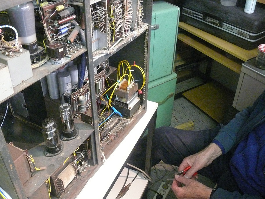
Fore it we first had to restart our Nachtfee console, which caused some problems; viewing backwards, we encountered already in the passed a mall function of the console time-base deflection system
I must admit, that I don't know exactly yet what is mall-functioning, but at least I know that it concerns Rö 8 (EF 14); maybe the parallel capacitor parallel onto its deflection output transformer. Its circuitry is very difficult to access.
22.

However, it operates currently fine
When this stage fails, the HT at the EF 14 anode remains about 360 V, but no signal being provided.
23.

The 1:10 prove is still connected onto the Rö 8 anode and the meter in the background is indication the voltage across the EF 14 cathode resistor
24.

This experimental session will now be closed, and we would like to introduce a for us new technology as being used inside the Nachtfee console
25.

Using experimentally the circuitry as is maintained in the Nachtfee console; but because no values being provided, we considered the Lichtenstein FuG 202bc circuitry, as for the latter we possess indication of the variable tuning capacitors.
The two tuning capacitors are according to the FuG 202 bc schematic, facing the G1 ca. 40 - 5000 pF and the one connected onto the deflection cylinder ca. 2000 pF (our capacitors are providing a wider capacitance range, but both allow well adjustments within their mutual tuning ranges)
(Thank you Peter Kievits)
28.

We disconnected the clamping circuitry as well as the high-lighting (brightening) circuitry; but adopted two variable capacitors of German origine
And, we were astonished how well it works, and making the brightening circuitry redundant.
The crux is - to supply the video - pulse at the same time, onto the g1 as well onto the circular deflection cylinder; it has to be find out the amount of signal ratios between G1 and the circular deflection cylinder.
26.

We encountered a wonderful video presentation, making external brightening signals redundant
27.
(3) (since 3 July 2023)
On a rally on 24th June I obtained among other things a new type of mica trimmer condensers, which might fitting better in our modified system concept

Each box contains a mica trimmer tuneable between ca. 30 - 4000 pF
Once manufactured by Siemens.
The blue series capacitor is only implemented for safety precautions as on the left-hand device onside is directly connected onto ca. 2 kV; albeit that the current has been limited by means of a 1 MΩ resistor, thus maximally resulting in ca. 2 mA current.
The metal cover is insulated from what is inside.
28.

We tested it wired inside our existing experimental (pertinax/phenol) mounting strip
The small board in front constitute 10 zener-diodes in series which are being fed via the fore called 1 MΩ resistor reducing 2.3 kV HT to ca. 2 kV HT fed onto the circular deflection cylinder of the LB 2 crt
It proved necessary to stabilise the crt HT as the the brightness control was, otherwise, too much blurring the painted signals.
It seems that we can integrate both Siemens trimmers inside our new acryl display
29.

The modification drawn by means of a pencil into our first concept schematic
30.

The idea matured by studying the way the Nachtfee Consol provisions
The crux seemingly is tuning the injection-voltages onto both the g1 (= Wehnelt cylinder) as well as onto the deflection-cylinder of our circular LB2 crt
What we couldn't manage with the two forgoing mica trimmers, is now quite simple to manage with the two Siemens trimmer.
There clearly exists a particular ratio setting between the two video signals fed onto g1 as well as the anode cylinder.
I suppose this is being caused by the slope curve of the signal fed onto the g1 and the voltage fed onto the anode cylinder.
31.

Viewing it from a slightly different perspective
32.

Visible is the aircraft simulated display, but truly showing the actual 0° phase of the Nachtfee aircraft time-base
Used to indicate on the Nachtfee control-screen the actual status of the air-craft time-base reference.
This pulse is essential as by means of this reference the console operator can adjust the signal phase transmitted towards the aircraft transponder.
As to guarantee that the Nachtfee order arrives just at the correct instant at the aircraft display, the Nachtfee signal has to be phase shifted correctly. Hence, the Nachtfee consol needs therefore to know what the actual status of the aircraft time-base is
For a full explanation - please consider my: https://www.cdvandt.org/nachtfee-v6-mp4.htm
33.

Showing the the current test set-up
34.
(4) (since 30 August 2023)
Hans Goulooze has during the summer period prepared provisions for our Nachtfee aircraft display reconstruction.
We have two major concerns: the layout and its realisation should be sound.
Though, the components should be arranged and mounted logically, and the cabling should be wired optimally.
Soldering, when the acryl, or whatever mounting carrier-plate, is attached is to be prevented.

This essential plate is to be used for exact positioning of the drilling-holes
35.

Designing a circuitry fitting together is demanding special skill
36.

It looks all quite simple, but it necessitates a sound dimensional skill
37.

The next step is mounting the partly wired circuitry exactly on top of the drilled holes of, ca. 3.1 mm
When you view this photo carefully you might notice the slight transparency difference of the acryl or polycarbonate mounting (montage) plate.
38.

Viewing our mounting plate from its bottom-side; the 3 mm screws will be tooled in the reconstruction of our acryl aircraft display frame
Please notice the schematic of the LB 2 circular deflection crt on the far right-hand side.
39.

What Hans designate Empfänger line, actually is the video signal
Viewing the mounting plate from the top position.
The cables pointing towards us, being connected onto the LB2 base
Whereas the to cables point upwards being meant for the two controls for:
brightness
and
focus
control at the tiny front panel
40.
The spacing of components looks like a bit too roomy, but please bear in mind that at some lines we encounter ca. 2 kV anode voltage fed onto the circular deflection cylinder.
The LB 2 CRT internal connections are partly visible on the right-hand side of the contact-strip. This crt is provided with a circular deflection yoke system.
(5) (since 8 September 2023)

On 7 September 2023, Hans Goulooze continued with preparing the future wiring of our Nachtfee acryl prototype
41.
The purpose of this current contribution is - to show you the progress Hans Goulooze's commitment is making
Very important is to approach this beautiful acryl display soundly, as to prevent for un-necessary damage.
Even minor mistakes cannot be corrected afterwards.
42.

Viewing the right-hand side of our future aircraft display construction
43.

Viewing the acryl display construction from different sides
44.

Moving the perspective more towards the front-panel
45.

Considering now the left-hand display side
46.

It proved necessary to stabilise the 2 kV high-tension, because when CRT screen brightness changed also the trace focus responded negatively
Therefore we increase the supply voltage to ca. 2.3 kV and wired in series an 1MΩ resistor, this was loaded by 10 x 200 V zener diodes. Through the 1 MΩ flows only (U = I· R) → (I = 300/106 = 300 µA); consequently through the zener diodes is flowing even less as also the LB 2 crt system circuitry is constituting a current load.
It proved to operate smoothly and
47.

About this position we plan to fit our CRT 2 kV supply stabilisation
48.

Considering the current working conditions; which should, Deo volente, change next weekend 9 and or 10 September, as to prepare room for our scheduled Secret Communications 4 exhibition
49.
(9) (since 6 October 2023)
On 5th October Hans and myself went to our subsidiary location called: MLK; where we have among other utilities also our depots, library/archives, and our mechanical- and electronic workshops.
Our lath isn't operated often, since about two decades
A splendid opportunity to revive it again, albeit for today at least

Our Mayford Lath type 7B is a metric version
50.
The aim today was to cut the acryl tube into 10 mm and 5 mm "stand-offs"
As our superb acryl is so nicely build, all mechanical attachments need to be as meticulous as is its acryl frame work.
Because Hans isn't used to our lath machine, it takes some time before Hans does understand the main adjustments.

Our lath is fit with speedy exchangeable chisel-holder, which easily can be adjusted against its chisel-to-lath centre (excuse that I don't know the English proper expressions)
51.

Maybe you understand the meaning of the adjustment explained clumsy in the foregoing photo
52.

Viewing the foregoing photo slightly differently
53.
Lath adjustment has to be accomplished accurately, and Hans was still building up his touch with our unknown Mayford 7B lath (with attached 'Norton metric gear-box)
I suppose, Hans is actually watching the 'nonious-scale'
54.

Hans' first experiments were accomplished without utilising protective paper wound around the rather sensitive acryl tube
55.
The acryl tube being fixed and Hans did start cutting equally sized 'stand-offs'
56.

The main concern is, to cut-off each 'stand-off' equally
It does makes a difference whether their seize is 10.0 or say 10.3 mm as long as all 4 'stand-offs' being equally seized.
57.

I suppose, that with the foregoing brief descriptions you do understand what it is all about
The paper is necessary as to prevent the quite soft acrylic tubes being scratched.
57.
↕
Please notice the circuitry mounted at the longitudinal acryl plate mounted underneath the LB 2 crt preliminary, at the acrylic main chassis; which is resting on 4 black rubber 'stand-offs', which should be replaced by the just manufactured our Mayford Lath, by Hans Goulooze
48.

Both end of each acrylic tubular stand-offs must also be polished accurately
The first step is using the finest sandpaper.
It is easily visible that two types of 'stand-off' being used
58.

Hans prefers sandpaper type 1000
59.

The finishing touch is accomplished by means of so-called 'Sorbo tissue', as polishing paste he uses 'metal-polish'
Our aim is to get the cut-off tube-ends a clear as the acryl display entirely is.
A meticulous careful job!
60.

Hans' way of polishing is quite clear and understandable
61.
(10) (since 20 October 2023)
Today 19 October 2023
We have continued today with making plans for the continuation of the final wiring of our Aircraft display reconstruction.

62.
Shown here is an edge connector of the type Amphenol did introduce in the 1950s; but which's actual design is of German origin
These had been produced by the firm "List" and had been , after the war, widely copied by the Russians and French manufacturers
even in a way, that these copies were fully replaceable by the genuine German samples vice versa.
Amphenol in the US, took over the concept-basics, and brought them with success on the international market.
The Germans operated mainly: 6 - 14 and 20 pin-versions.
The shown type above is providing 14 wire connections.

63.
Al sorts of preparations has to be accomplished: especially concerning the signals and HT fed onto the various edge-connections

64.
It is a quite painful en careful process as to ensure that all pins being rightly and most efficiently wired

Viewing the process from a slightly different perspective
65.
It is necessary to work as clean as possible, as 'acryl' is a beautiful sound material but it would be shameful to cause unnecessary scratches; which being hardly possible to restore.

Hans is time and again checking the plug connection numbers versus their signal functions
66.

There are quite many different signals to be dealt with:
12.6 V for the LB 2 crt
2.3 kV HT for the crt circuitry (after stabilisation there remains 2 kV), incorporating plus and minus 2.3 kV
The two: sine and cos sign deflection signals - necessary for the circular crt presentation
The video signal for the command and aircraft time-base control also send towards the virtual Nachtfee ground station
Various 'ground-level' interconnections
67.

Viewing it from a slightly different perspective
Please, notice the nice way you can view to what circuitry is inside.
The white colour backgrounds (also in the foregoing photographs) actually constitute paper-sheets as to prevent damage of the sound acryl surface.
68.
Please consider the next photograph again:
Please notice the reconstructed transformer substitute:
I measured some days ago the outside temperatures - firstly at the brown 'oil-paper' facing towards us (just above the transformer-core and where the paper is starting to be rounding).
It proved that after, say, 90 à 120 minutes had risen to ca. 41° C.
and the core-temperature in the middle of the section facing towards Hans
I measured ca. 39,..° C.
We consider this operational temperature as being sufficient.
Our Nachtfee console on display is running now-and-then, and will hardly be demonstrated for more than two or three hours continuously.
(11)
(11)

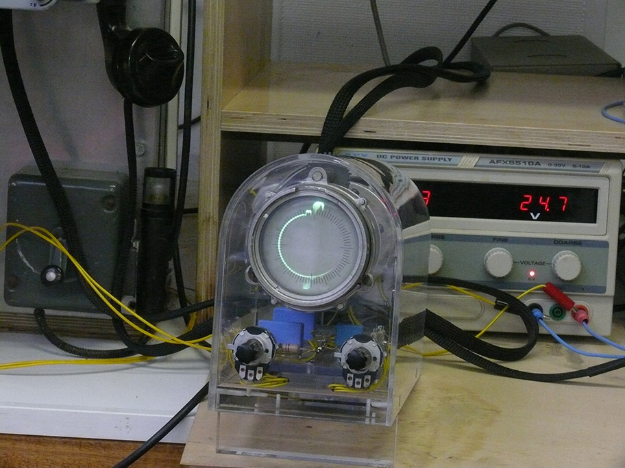
Today, for the first time Hans brought in his completed, though, not yet tested Acrylic display
(69).

Today I prefer to take a bunch of photographs, with a minimum of explanations
(70).

The two square metal boxes cover two mica variable capacitors which together determine the shape of the video signal 'blip' on the circular screen presentation
This wasn't yet foreseen when we designed our proto-type display
(71).

Viewing the new display towards the rear panel
(72).

Hans really accomplished a great job!
(73).

In my perception it is like a dream; planning so for about a year and that it finally matures in such a beautiful artefact a miracle
(74).

Hans gave me today this photograph to show the way the "List" type edge-connector has been wired
(74a).

Acrylic is a wonderful material, which demands special careful handling; as fault hardly can be revised
(76).

Considering it from a slightly different position
(77).
Please bear in mind, that this drawing of about May-June 1945 was the only reference we have; and this is what we, freely interpreted
↓

Now the curved acrylic cover being mounted
It looks a bit grey, but this is only being cause by reflecting the white sealing pattern; please notice the accessible tooth-wheel on top; which allows us to rotate the deflection yokes for +/- 10 degrees, as to align the 'time-base reference pulse to be aligned at due north (0/360°)
(78).

Noticing our display from a slightly different angle
(79).

I can't get enough impressions were we have waited for about one year, in casu, the concept in someone's mind and the recent realisation
There does not exist great difference in the main lines of concept
(80).

One word: beautiful
(81).

The vertical 0/360° compass line had been designated at the genuine Nachtfee Order Compass by N (the aircraft time-base reference signal (blip) should be aligned by mean of the tooth-wheel just touchable at the upper acrylic-cover-slit
(82).

Viewing it from a slightly different perspective
(83).

Why should spoil words?
(84).

No comments
(85).
(12) (since 3 November 2023)

Hans wired the external display cable and reconsidered what he had once accomplished. He came to the conclusion, to change some connections, causing a quite complex reshuffling and testing process
(86).

The German List type edge connectors allow us to have optimal freedom in the way the connector is to be mounted
Think of: the male connector at the display unit, and the female at the cable side.
But also at will: the female at the the display side and the male end mounting on the cable side.
(87).

Hampering, sometimes is, that you van the notice the edge connector sometimes is mirror-wise counting
(88).

Two edge connections had been removed (connections 6 and 13) as to allow separation between the 2.3 kV and the re rest of the low tension wiring
Because the cable-end is providing the various voltages including the 2.3 kV supply, it is favourable to wire the female at the cable end.
(89).

Connector being completely counted
Our display unit is now ready to be tested.
(90).

It demanded some minor adaptations as to get the focus control operating optimally
(the reason was, that at the prototype we used 1 MΩ potentiometers, whereas we maintain currently 500 kΩ types.
After we had mounted our display at its place where it should operate, we discovered a phenomena, that the time-base line behaved differently than the above screen photo
It was discovered that this is caused by interference originating from our 24 V dc volt power-supply
(91).
Please compare this screen shot with that of photo (91)
After I lifted in the foregoing photo, our new acrylic aircraft display, the time-base line blurring disappeared after I lifted the display a bit upwards. The interference being caused by RF radiation originating from the 24 dc power supply. I had already straight from the beginning removed the top cover, as the build-in van did not provide sufficient cooling which simply switches off. After the top cover had been removed we encountered no head problems at all; albeit now we suffer unexpectedly from RF interference. Maybe an additional metal screen will solve our problems.
Hans suggested that an iron plate will screen-off this interference sufficiently.
(34).
(13) (since 10 November 2023)
On Thursday: 9 November 2023
we continued, first with finding out why the deflection signal of the time-base line; be it circular or horizontal.
However, I am not yet for 100% convinced that we solved all nuisance, but at least some.
A bit difficult to determine was: that the circular display gave to time-circle; and viewing its base from the rear, I did not see any sign of filament glowing. But carefulness is necessary as it is galvanically directly connected onto - 2 kV! It might, after all, had been a soldering problem at a LB2 filament base-pin.
Afterwards
It started to function again.

The bright pulse about 12 minutes passed the hour is the time-base reference pulse indicating the ca. 0° the start of a new circle rotation. This reference signal is essential, as for proper operation the ground station has to be informed what the actual system-phase of the flying pathfinder is
The signal phase received has travelled the from the flying platform to the Nachtfee Console system.
The Nachtfee Order/Command signal is the weaker signal just passing the hour.
The Aircraft time reference signal is not yet adjusted accordingly.
(92).

The only schematic available, more than we possessed some years ago; but the value of components is sometimes designated, say: 300
What value: 300 or 3000 Ω or 300 kΩ?
(93).

The pulse facing nearly due south originates from the Nachtfee Order or Compass command
The pulse-flank at due north is the time-base reference pulse which is being send towards the Nachtfee Console; as to allow proper "Phase" adjustment.
This is necessary as to adjust the Nachtfee ground-system against the (delayed) momentum of arrival of this time base reference again. Which first has to bridge the distance aircraft to the Nachtfee Console on the ground and finally to adjust it all thus, that the order or Command signal will be painted correctly in the time (phase) domain on the aircraft CRT screen.
(94).

A full size view at our current situation this early afternoon
(95).

What has to be checked also is what is the out/input of our left-hand side interface
Which has to handle bi-directional signals (from and towards the IFF transponder FuG 25a
(96).

(97).
Checking the out/and input of the left-hand side interface
Dual (by-directional) signals are available
On the one hand - the output of the FuG 25a transponder, though, on the other hand, the time-base reference signal (constituting the time-base-reference necessary to align the current signal-face (versus the time the signal travelling time necessary as to arrive at ground station electronics) on the from the which has to be conveyed to the Nachtfee ground Console.
The signal about due South is the about phase and distance correctly time/phase aligned ground station
(98).

This signal is the time-base reference signal supplied onto pin 9 of the in/output connection central control connector (the pulse prf is 2 ms; thus 500 Hz)
(99).

The signal die east corresponds with the current adjustment of the Nachtfee Command-pointer
(100).

(101).
The currently used Gemse IFF receiver, showed some decrease sensitivity
A simple remedy often is to readjust the tuning of the Gemse receiver; but the mechanical control did not cause any sign of tuning.
Therefore we have to investigate what goes wrong. One matter encountered was a too dried-up lubrication of the spindle.
Luckily, we possess a second, spare Gemse.
Afterwards I discovered that last year we did obtain from France a third Gemse receiver.

(102).
The current test setting is quite convenient, as we do not suffer from the magnetic flux jamming a bit the proper painting of the aircraft time-base-circle

Because we have experimentally mounted the display no longer on top of the 24/25 V power-supply we got rid off the magnetic flux is passing through the sensitive part of our display
Maybe, we to screen-off by means of mu-metal strips; which I luckily still kept from the early 1970!
(103).

Taking a wider vision on what we currently are doing
(104).

The last photo is only showing the more or less correct adjustment of the aircraft time-base reference versus distance and delays caused inside the various electronic circuitries which this signal has passed through
(105).
To be continued in due course
By Arthur O. Bauer
![]()