The GK IIIb scrambler system communicating
combined through a complete set-up of the carrier-telephony system Tfb 2.
Demonstration recorded on YouTube on 12 March 2020 in our museum.
Status: 13 March 2020
Updated on
Status: 16 March 2020
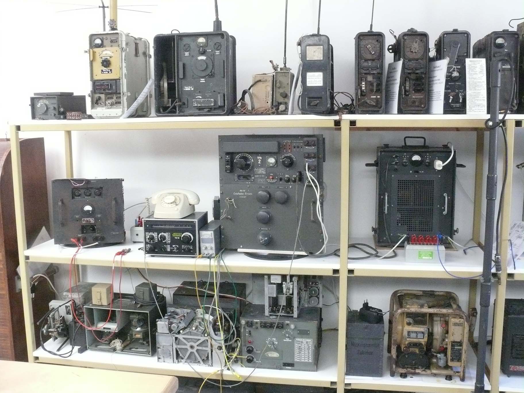
From left to right:
GK IIIb scrambler apparatus; T 65 type telephone on top of an audio signal generator; right of it the Tfb 2 carrier telephony set acting in station mode A
In the centre in the background the 12 V, magnetically regulated (accurate) genuine power supply
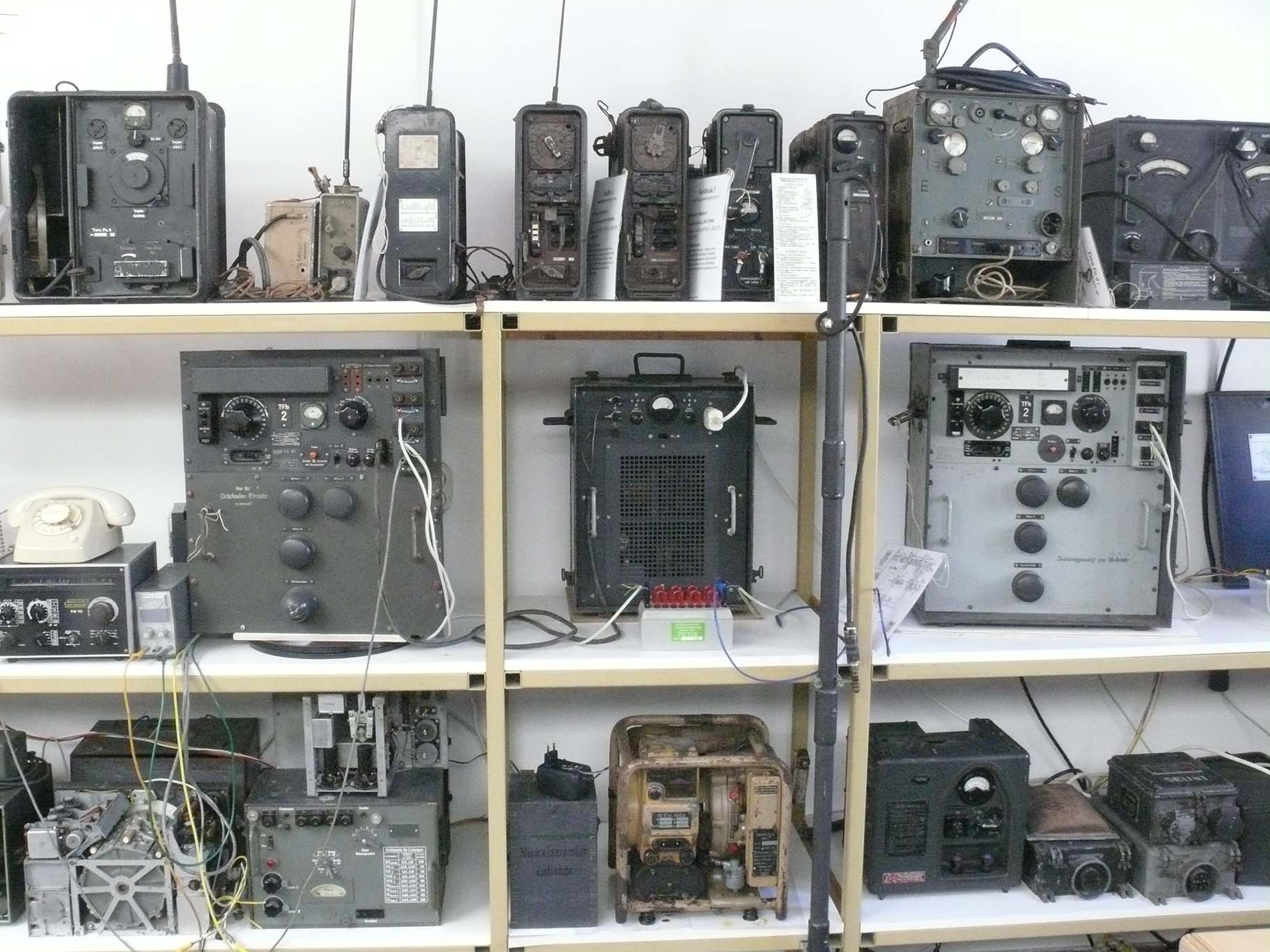
The light-grey tall module, is the second Tfb 2 carrier telephony set operating in station mode B

On the right-hand side of the light-grey Tfb 2 set, the second GK IIIb scrambler/de-scrambler
Speech/audio being reproduced by means of the two small computer loudspeaker next to the glass-window.
Our Tfb 2 restoration Survey has been, extensively, dealt within:
https://www.cdvandt.org/tfb-survey.htm
(1)
Afterwards I have decided, that the reproduction of the schematic of the Tfb 1, 2, 3 does make sense and therefore you find it next. For those interested in the schematic more in details you can click on the drawing and it opens in PDF as well.
Schematic of Tfb 1, 2 and likely also type 3
Please click at the schematic as to open it in PDF, allowing you to get a more detailed vision.
However,
Tfb 4 operating at 22 kHz, apparently necessitated additional amplification; sadly our schematic fits only to the three valves version, whereas the Tfb 4 employs 4 valves..
Please notice: you will hear a buzzing sound in the background - which originates from the vibrator module, converting the 12 V dc into HT dc voltage and other means; of the dark-grey Tfb2 unit.
The light-grey Tfb 2 set had once been converted for mains operation about 1948-1953.
This was done so extremely poor, that it caused an extensive job, as to let it operate properly again! (see the tfb-survey link above)

The self-explaining block diagram of the current exhibition set-up
On the far left-hand side the Type T 65 telephone (1965-1990s), which speech-current is modulating the GK IIIb type scrambler module.
The scrambled signal being fed onto the Tfb2 carrier telephony set operating in mode A. However, the signal had passed trough the a cable-equivalent (dummy) representing and equivalent signal reduction as once had been caused by 5 km PTT ground cable.
Before the first Tfb2's signal could reach the Tfb2 operating in station-mode B, it had to pass through a separate cable equivalence (dummy) (Kabelersatz) as well.
The output of the second Tfb2 apparatus is fed onto the second GK IIIb scrambler unit; we know - that twice scrambling is resulting in de-scrambling signal output.
Which signal is made audible by means of a set of simple PC loudspeakers.
YouTube films:
Film 00045: viewing the rather unique set-up. From left to the right the GK IIIb sending a scrambled signal. The first tall module is a Tfb2 carrier-telephony set sending in Station-mode A. The light-grey tall unit is the receiving
Tfb2 at operating at mode B. The scrambled audio signal being fed onto the GK IIIb operating here as a de-scrambler.
Film 00048: Self-explaining a bit more in detail. The phenomena of being shown where first two-times scrambling resulting in de-scrambling of the original audio content. Whereas, when one set being switched off, the second set on
the right-hand side is now scrambling the clear audio signal; resulting in a scrambled signal.
Film 00051: Explaining in a bit slightly different way, the operation of this unique system set-up.
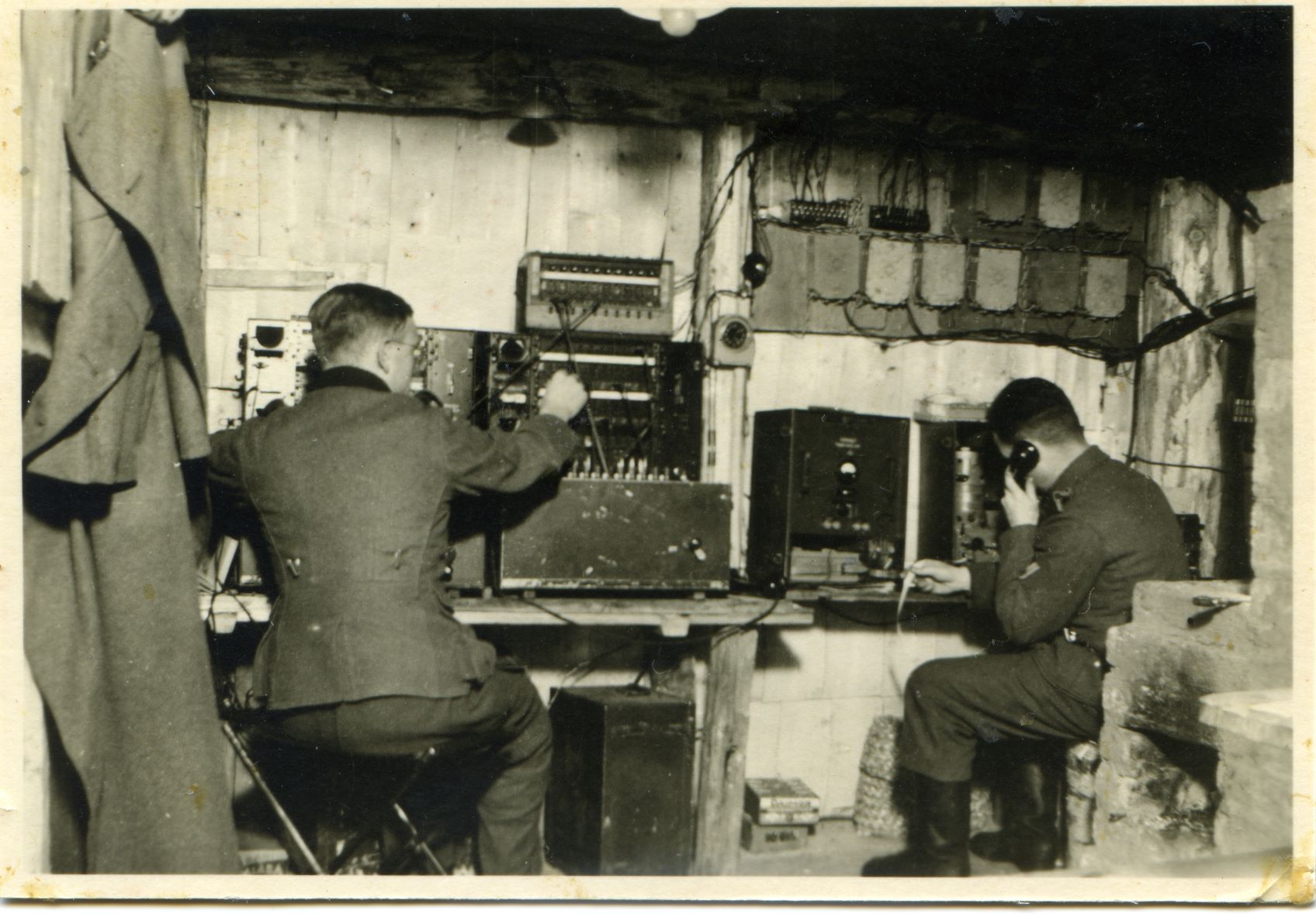
Fotosammlung Fastner
Last, but, Deo volente, not least, a genuine wartime photograph, showing a battlefield telephone-exchange behind the Rschew front-line in Russia.
Apparently the right-hand side operator is operating a Siemens Feldfernschreiber; and the GK IIIb currently was not used, as it had not been connected by means of wires.
I myself am, since 1976, a dedicated Hell-mode fan, and operating such machines in conjunction with genuine gear.
Nowadays, being forced to used for reception a "websdr" server.
Though transmitting is maintained still as is shown in the link below:
https://www.cdvandt.org/hell-pa0aob.htm
By Arthur O. Bauer
![]()