
U 224
The rotary convertor to the Berlin FuG 224 radar system
Converting (24-28V) into 80 V 500 Hz a.c.
Please bear in mind, that the genuine idea originated from a British engineer, who once claimed that an optimal energy conversion would be accomplished at 80 V ac about 1700 Hz?
The Germans copied the idea, but, likely due to practical reasons, the kept 80 V ac supply, but at 500 Hz. I suppose, for quite practical reasons, because they might have suffered from sufficient quantities of permeable alloys.
Status: 25 June 2018
A newly corrected schematic of the power system of the Berlin FuG 224 radar
Production code-number: 365308
GAF stock number: Ln 29648
Manufacturer
code: omp
One might read: amp; though this would refer onto: a steel plant
Considering
several combinations, the most likely one might become: OMP
The latter stood once for:

I suppose Kamitz
sounds, in my perception, Sudetenland like (nowadays hold by the Czech Republic)
On 28 May 2018 Werner Thote responded in an e-mail, on the query who was once its actual manufacturer?
He wrote:
Du suchst den Hersteller "omp". Das ist ein Lesefehler. Der erste Buchstabe ist über die Grenze der erhabenen hellen Fläche auf dem Typschild hinaus eingeschlagen. Der Buchstatabe "d" wird deshalb ähnlich einem "o"
abgebildet. Richtig ist "DMP". HERSTELLER: ELBTALWERK ELEKTRIZITÄTS A.G., HEIDENAU-DRESDEN, 30 Minuten Autofahrt von hier. Ein wesentlicher Hersteller von Umformern.
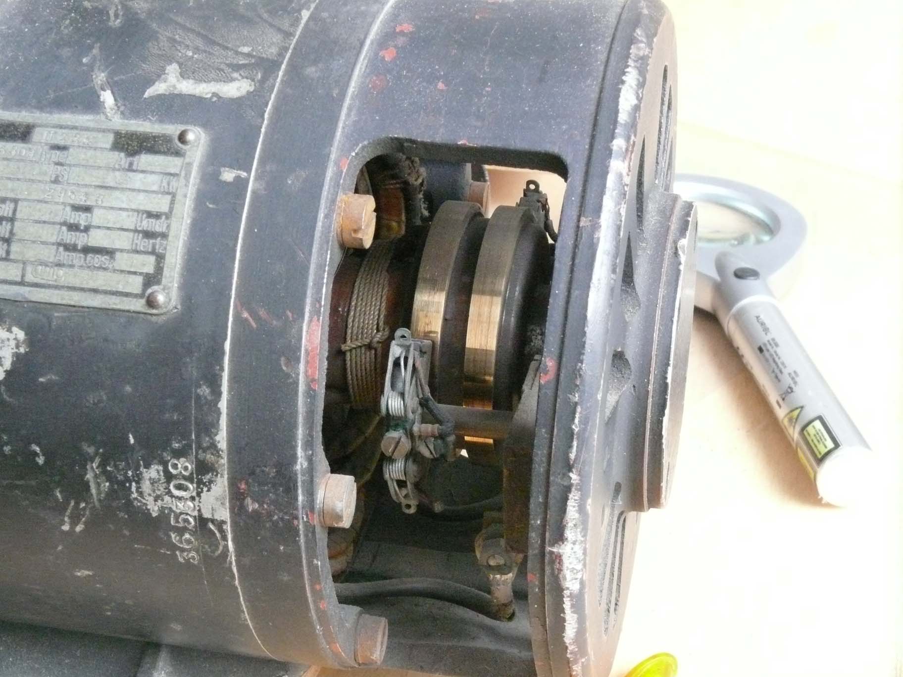
It has to be said: that the interior looks quite sound
Viewing the 80V ac section, providing 80 V 500 Hz.
Please notice the number on the left-hand side, which equals the one at the type-number plate.

Please be aware: that under load conditions, this rotary convertor consumes 27-28 V 80 A! Looking at the bearing cover-plates: these seemingly have never been touched since production.
We decided therefore, that we should leave it in this genuine state.

The chance that we would operate this device is about null

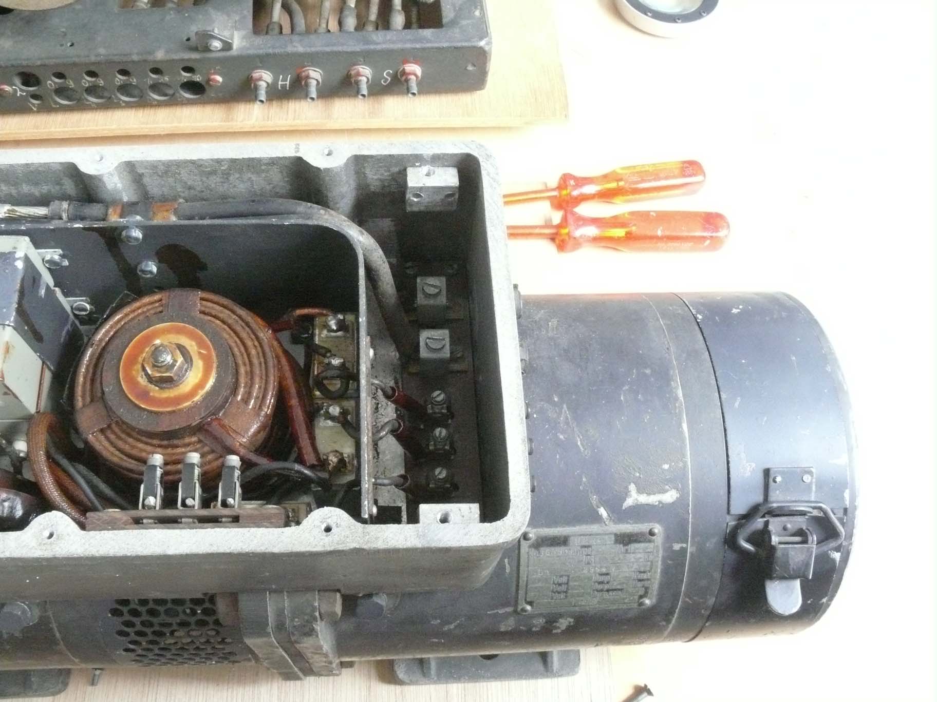
On top of the Berlin radar "Umformer" we find an elaborated (current) suppressor filter compartment
On the left-hand side the section for 27-29 V dc, but working load being approx. 80 Amps.
On the right-hand side the filter for smoothing the 80 V 500 Hz output circuit.

Clear is, that all being constructed solid
Noticing the two rings attached onto the rotor, we are dealing with a single-phase system
Therefore, I
suppose, that one of the three output contacts (80 V 500 Hz) being connected
onto the "ground" of the system.
(B)
Let us first consider photos showing the Umformer more as a unit, rather than details.

Its overall length 56.5 cm

Its diameter 15.5 cm

Viewing it differently

Quite a heavy beast isn't it, weighting 38 kg!
Now a bit more technically
(C)
On 25 June 2018
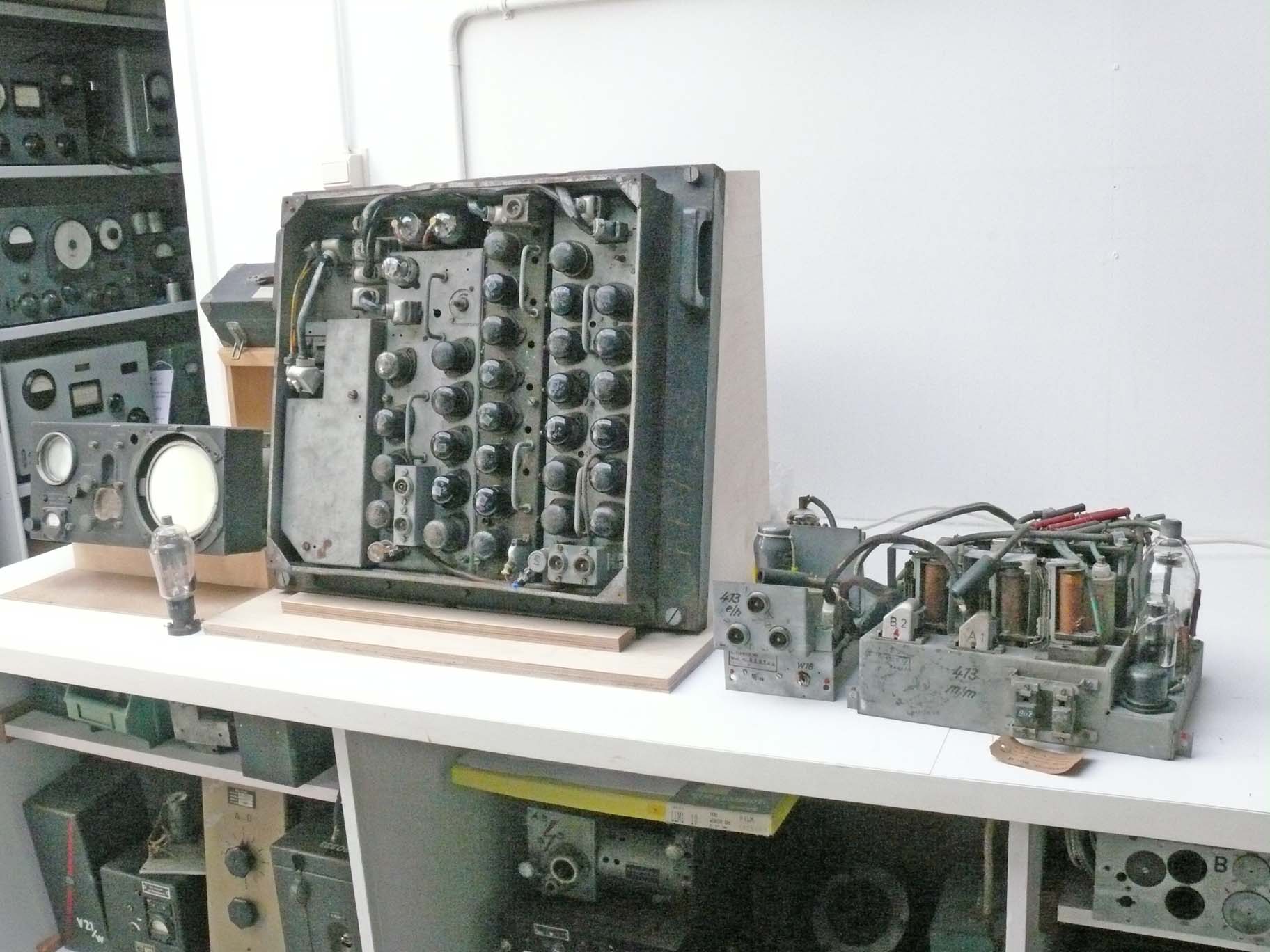
Florian Eibensteiner was so kind to send me some additional information

Today 25 June 2018, Florian Eibensteiner very kindly provided Berlin schematics, among it this one (this time derived from an original wartime trainings paper)
The 80 V ac originating from the U224 output.
SI stood for Sichtgerät also known as PPI display, shown on the far left-hand side of the next photo
Up on the right-hand side of the schematic, the output of controlled 80 V ac.
U 1 is acting as a current transformer; likely for safety measure. In case of overload the system should switching off itself.
T 1 is within Feld II (see below)
I hope the schematic is self-explanatory .
Feld I is the square frame more to the left
Zündstufe just next to the Feld I frame and the medium/high voltage power supply is the module on the far right-hand side.

An original photo of a captured Feld II frame
By the way also supplied with 80 V ac 500 Hz (via Tr 1).
To be continued in due course
By Arthur O. Bauer
![]()