
For your own convenience, we would like to advice you to use a search mode window when you would like to access particular data in a fast way
for Windows users: Ctr + F
and for Mac OS X users: Cmd + F
Entre your particular search word and all those words inside this document will be successively shown
Würzburg radar repair report
(Wurzburg)
An extraordinary Technical Survey
Status: 20 March 2013 (in progress)
A
Our Würzburg FuSE62D did function up to about 1990, then it struck and we have left it being this way since
After we had moved to the new museum premises, the idea came up - that it would be a challenge bringing our, still wired, Würzburg apparatus to live again, be it eventually for a single occasion. After all other major projects were more or less finished, Dick Zijlmans and I started working on it in early November 2009. First, Dick had to re-connect all wires, as these were cut at particular places. Be it appropriately labelled like: A-A, B-B, C-C and so forth. After this was done, first our attention was drawn to the central stabilised 180 V ac power source. Würzburg uses two voltages (mains is single phase 220 V ac), though the most important one is the 180 V. This was done by simply placing in series with the 220 V ac line a so-called carbon-pile-regulator (acting as variable resistor). The system works on the principle of carbon-pile rings, which are being pressed together such that the central 180 volts is, under working conditions, kept at about 180 V ac (within say 1 volt). The Germans called these kinds of regulators "Pintsch-Regler". This value is only available as long as all sub-systems are operational. Thus the carbon-pile will provide a higher output voltage in the starting up phase, as long as the actual current is too low. This situation was indicated to the radar operator by means of a special red lamp at the front panel of the so-called Bediengerät 62 (BG62) (central control panel). Then he had to step down or to step up the supplying voltage (by means of a sort of Variac) until the red lamp extinguished. However, we do not possess a BG62 module and we have skipped this option. In our situation with full load we got only 169 volt. After due considerations I decided to re-adjust the pressure of the carbon-pile. The 180 stabilised ac voltage is now within the appropriate range.
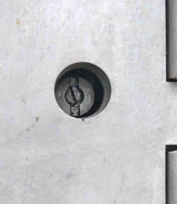
NR62 (Netzregler) also known as Pintsch-Regler
The adjustment screw is about the yellow/green wire, thus on top of the carbon-pile. Dick Zijlmans will, of course, clean the wiring after we have finished the overhaul of our Würzburg installation. Please notice also down the schematic of it.

To get optimal drawing quality, please click on this drawing
The power circuit of FuSE62/65 radar system
The Pintsch-Regler is called NR62 (Netz-Regler 62)
B
Our next move was trying to get HF output of the transmitter. This proved to be very difficult. Very safety precautions have to be taken, as the anode voltage is 8.3 kV and the grid blocking is -2.1 kV (being only 3750 times for 1 (1.8) µs at ground level, thus with a ratio of 1 : 333). The HT power supplies are designed to provide very high currents for > 1 or even 2 amperes. After some time I discovered how the anode circuit of the LS180 transmitter valve actually worked.

I did not well understand the implications of this circuit. I finally came to the conclusion, that it worked just opposite as I thought. The anode current is directly provided by means of the charging current through the capacitance of 0.05µF (C6). The three resistors in series is only for de-charging the capacitor during the duration of pulse-pause, in casu during the receiving interval (333 : 1). Wouldn't the resistors be there the capacitor would have been left charged. In other words, the discharge should bring both capacitor electrodes (plates) at a voltage level of 8.3 kV versus ground.
Let us calculate the stored energy inside the capacitor after the transmission impulse is going to rest:
J = 1/2 C.U² = 1/2 . 5.10-8 . (8.103)² = 1.6 J (joule)
This amount of energy must be reduced to the lowest value possible, within 1/3750 s (constituting the PRF, 1 : 333). Here grips Henk Peek's comment: That there remains a voltage of about 96 V having a rimple (ripple?) of 40 V. *(very down this page)
Henk Peek also pointed, that the R/C arrangement is also acting as to protect the LS180 for the case that, for what ever reason, the blocking pulse is faulty. The resistors will limit the maximum anode current at 0.5 A. Still representing 4 kW power consumption! However, the automatic fuse-switch will soon block the 8 kV power supply.
It is also clear, that the saturated valve will never having 0 V at its anode, as the Ri of the LS180 is limiting this phenomenon. But for understanding the circuit principle we may neglect this minor factor.
We were amazed, however, that the capacitor parameters were still within its specs, after about 65 years! Remember, it has to operate at about 8.3 kV and providing say 2 amps per pulse! (sealed-off high quality Siemens & Halske HT capacitor type). I integrated straight from the beginning an additional regulating transformer (Variac), by which means we can control the anode voltage at any value between 0 and 8.3 kV. This is very handsome. The high tension is for this occasion measured by means of an electrostatic voltmeter. Which can measure up to 6 kV, but does not cause problems when 8.3 kV is put on it! The advantage of such an electrostatic meter is, that it does not consume energy, as the method is entirely currentless. The only (tiny) current is flowing when the relatively small capacitor plates inside the instrument is being charged or discharged). The filament voltage of the tungsten cathode has to be adjusted within 1% accuracy. For this occasion we used a special moving-iron type instrument (0.5%), which is capable of handling even distorted voltages. It was set at exactly 6.2 volt, which value is for each LS180 valve individually indicated on the glass envelope (may be sometimes even 5.7 V).
However, this did not solved the problem of not getting any HF output! We both first thought that our LS180 transmitter valve might have passed away. How could we check this? Please consider, that this very special transmitter module is covering the spectrum between about 490 to say 580 MHz. The initial length of the filament wires is part of the cathode circuit for HF. Its total (actual) length is adjusted (tuned) at 1/4 λ, which constitute a low impedance for a particular frequency. For all other wavelengths it is having a high impedance. When the transmitting tube LS180 has to be replaced, the synchronising mechanism with that of the grid tuning must be disconnected. With all unforeseeable implications. However, after due considerations, I decided to disconnect the grid blocking voltage, by simply de-soldering the wire from the connector first. I know, of course, that this is a very crude measure, though, I wanted to see whether the valve would start having sufficient emission. We soon observed that the zircon-anode was becoming red, which is a certain proof that the cathode is capable of providing sufficient current.

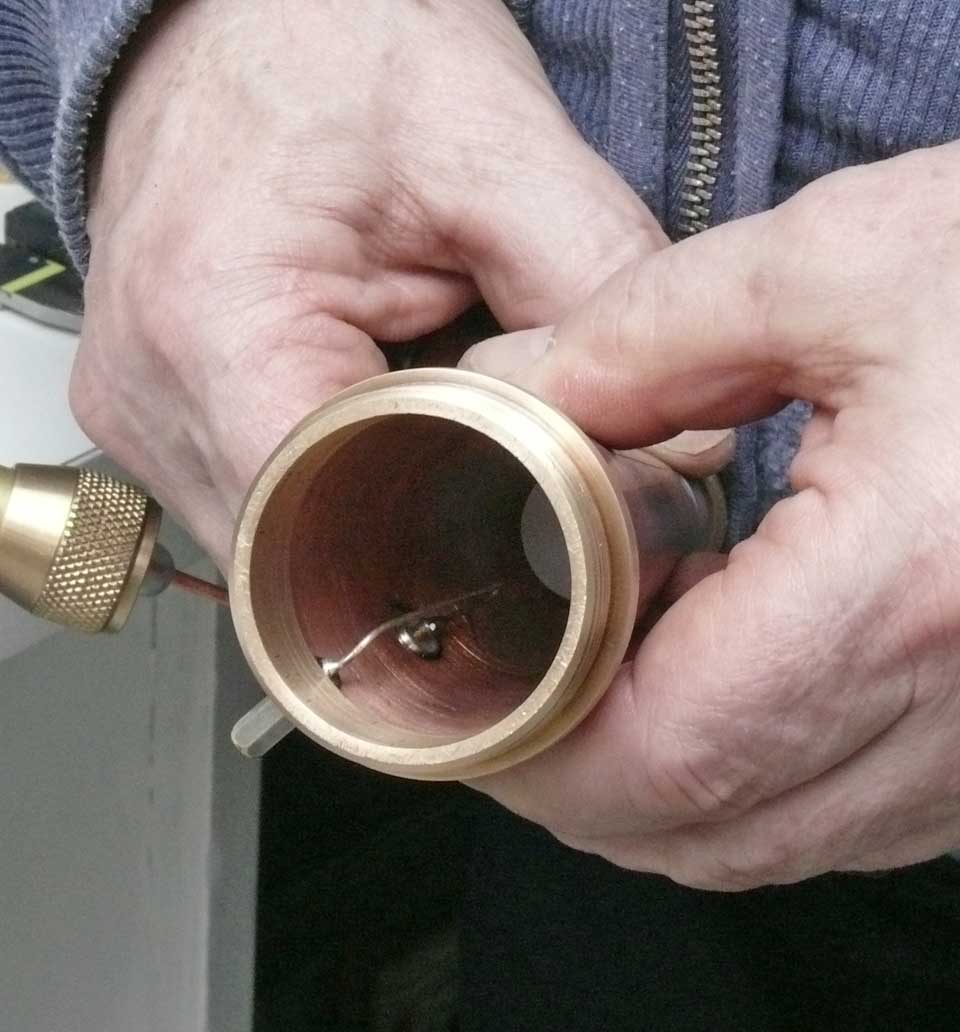
Cathode tuning circuit.
The controlling gear wheels with their markings is shown. Simply disconnecting and removing this section is quite complicated. The link just in front of the copper cathode tuning, is for injecting the coherent signal, which is generated in the HS62 (Hilfssender). By which means it is possible to synchronise the transmitter signal, as to allow Doppler signals to be received (detected) on the radar screen (Würzlaus or Tastlaus).
In a final desperate move we investigated the transmitter circuit more closely again. After the unit was removed from its mounting frame (rack), we guessed (wondered) where a Bakelite disc was for. I then realized that it was to link a remote tuned trimmer of the positive feed-back between the anode and the grid circuit. Which remote (tune) mechanism is not available in our set-up. After changing its initial capacitance "Eureka" the transmitter started working again!

The toothed brown Bakelite disk has to be re-adjusted, before the transmitter could start operating again. It was set by means of a worm-wheel mechanism accessible from the rear. C 2 is one half of the positive feed-back-trimmer between grid and anode (the latter is where we look at). L2 is very curious, in my opinion maybe the most unique circuit of its kind. L2 picks up the transmitter energy by simply 'influence'. One end is open and the other end is connected onto Bu 3 towards the coaxial strip-line in the rear section. The shape of the anode inside the LS180 is clearly visible. The handle left of 'Rö 1' is to set the transmitter frequency, tuning in concert both grid and cathode circuit.

C 2 is the capacitor that did trouble us. It had to be set such that a bit more feed-back between grid and anode was provided. From the schematic we can see that this also allowed frequency fine tuning. The frequency handle is to set coarse frequency whereas the tuning at the rear is for adjusting the working frequency more precisely

The grid/anode tuning of the Urechse transmitter SÜ62d. The ceramic spindle is on the right linked onto the cathode tuning mechanism; what we see is the tuning of the grid/anode circuit (pertinax strip with a short-circuit block at its end) which coil strip is on the left soldered onto one section of tuning trimmer C 2. Please notice the filament voltage of 6.2 V on the valve envelope. The output coupling strip line L 2 is also clearly visible
Please don't forget to click on them for optimal reproduction

Measuring the frequency and proving that real HF energy is fed onto the Heatkkit dummy-load. The wave meter is for this occasion an original wartime R&S type WAR covering up to 700 MHz. A curious detail is, that it possess no external connection, but the 220 V mains wire. The HF field is passing through the wooded box and is there being picked up by the tuned circuit inside the wave meter. Please notice the neon-bulb on top of the dummy-load, which is indicating HF contactless. I known, that there exists a mismatch owing to the fact, that the dummy-load is having 50 Ω and the antenna cable is constituting 70 Ω. The connecting cable is rather long versus the wavelength involved. Thus the transmitter is not having problems with it. We intend however, in a later stage to connect on occasion this cable onto the original Würzburg power meter (Ln20978)
During our work on the transmitter we also suspected the pulse generator, which provides the 2.1 kV negative pulses of about 1 (1.8) µs (1 : 333). I learned much from this survey. One important matter is also, that the central 12.6 V filament transformer is not being housed in one of the two main power supplies NA I or NA II though, is inside the impulse generator known as: IG62a (Impulsgenerator). I must certainly have known this twenty five years ago, when I made (designed) the entire wiring of the Würzburg system!

Schematic of the pulse modulator type IG62a
To obtain optimal reproduction quality, please click on the schematic diagram


The upper screen picture shows the gating pulse of the transmitter (1μs). The lower one constitutes the receiver blocking pulse during the transmitting pulse as to protect the receiver front-end and minimising the recovery time of the IF amplifiers. Both pulses are derived from the capacitive divider of the - 2.1 (2.3) kV stage. - 2.3 kV is on the cathode circuit, whereas the anode of the LS50 valve is at ground level. The actual pulses are being measured at the end of the circuit output, ensuring that they are really existing. The receiver blocking (RX) is having broader shoulders as to guarantee that the TX pulse is always within the receiver blocking time frame.
C
In the course of our work, we also had to deal with the problem that the required + 350 V was too low (310 volt at maximum) (NA II). After due considerations, we decided to by-pass the rectifier bridge by a bridge of modern rectifiers (8 x BY255) (leaving, of course, the original bridge fully connected). For safety reasons, I have put two diodes in series of each bridge leg. The current through each bridge-leg may just being on the edge of what a BY255 can provide, as the power supply can deliver up to 2 A. However, we considered that our system is only being switched on for minutes so that the diode junction temperature would not have to exceed its limits.

NA II Power supply principle diagram
Please remember that a click allows better reproduction quality

The discs arrangement is the 350 V bridge Gl2, which is by-passed by a set of BY255 diodes (see text)
Please click on the drawings as to get the best reproductions
The by-pass diodes are mounted just at the output of transformer Ü2. The forward conductivity of these new diodes is much higher than the wartime types. We had to keep the voltage as low as possible (actually 365 V) by means of taking the lowest transformer tap possible.
When we started working on Würzburg again, we discovered that relay R1 in series with the 350 V supply was not responding without some mechanical help. This current sensitive relay is responding onto the current consumption of the pulse modulator type IG62a. After we lifted the supply towards 350 V, this relay R1 responded within milliseconds after the automatic fuse to IG62a is being activated. This relay has an important function, as it guarantees that pulsed minus 2.1 kV and +8.3 kV voltages is appropriately available before the transmitter SÜ62d type Urechse is switched on!
D
Our front-end RX and TX type 'Urechse SÜ62d' is very rare, to my knowledge this is the only one existing in the world (this type does allow fast frequency change at will between say 490-570 MHz). Hoffmann-Heyden photographed this one, together with our EAG62 - ANG62 about 1953. The regularly employed transmitter receiver front-end was called Eidechse (SU62a,b,c). Although, we have this type as well in our collection, we prefer to show the most advanced version. Both transmitter types used TX valve type LS180.
Please compare both schematics. The upper one is the generally used type S 62 carrying code-name Lokomotiv. The same type that was captured during the Bruneval raid. The lower principle schematic is of the improved Urechse (SÜ62d), the one where we are now concerned with
E
Checking the receiver chain next, consisting of the front-end inside the module SÜ62d and the IF amplifier ZFV62 (Zwischenfrequenzverstärker)

Basical schematic of Urechse SÜ62d
In the centre section is shown the mixer stage, with next left of it the first local oscillator. On the far left we see the wave meter.
The mixer is protected by means of two T/R cells, known in Germany being so-called "Nulloden". Please regard for further information my Airborne radar paper

The upper situation is showing the case where the transmitter is running at 1 (1.8) µs pulses. The Nullode cells (LG71) become then ionised internally and are acting as being a short circuit (detuning the 1/4 λ stubs). The lower one is explaining the case when the receiver has to pick up the returning radar pulses, and that the transmitter must be virtually not visible and further matching the coaxial strip-line requirement for 70 ohm at both antenna input and receiver input. Important to notice is, that the results are obtained for the case that stubs or lines can be regarded having a low or high impedance versus wavelengths. Please notice the original Nullode patent, which had been confiscated for decades in the US, that is why you will see a most rare document. Owing to the fact that already the Third Reich had sometimes confiscated these kind of significant patents (not in this case, which can been seen as Telefunken's name has not been deleted): DE761708 The principle of the T/R switch in combination with open and electrically shortened stubs is patented by DE881812 and DE897857. To activate the hyperlinks please click on the high lighted text sections

The Nullode type LG71
This sample has an extra facility by which means it is possible to pull it out of a coaxial space. For the two LG71s we use in our Urechse, I had to remove these silvered tubes. The inner part of the glass envelope is to hold the 1/4 λ stub. The outer side is screened off by a metal (coaxial) tube, which acts as ground. When the coaxial inner conductor is having sufficient EM field versus the outer conductor, the low pressure water vapour (≈ 1 Torr = 1 mm Hg) inside the Nullode LG71 is becoming ionised. Nullode originally means in German language: contactless device (no electrode - 'Null Elektrode'). On Internet you can find a photo of LG71 without having this silvered tube (puller?) see also DE761708
LG71 is switched on by the existing HF field surrounding the coaxial 1/4 λ stub (protecting the receiver front-end). Thus causing de-tuning of the stub which now acts as if the 1/4 λ stub is short circuited to (against) ground at its open end. Both the inner stub and the outer screening tube is clearly visible. The coaxial line impedance is determined by the ratio between D : d, where this must be about '3', which equals 70 Ω in free space (I have not yet measured whether the dielectric value ε of the glass tube was taken into account. It is, however, not entirely certain that the impedance actually is (has to be) 70 Ω, though we may expect that it is. The trimmers down of this photo belong to the 25 MHz IF band filter . Please consider also our "Patenets DE page" and search for 'nullode' patents DE761708,
F
Let us first continue with the receiver chain. The mixer valve LG9 is first to be dealt with (just visible left in the previous photo).
The mixing signal generated by the local oscillator is fed onto the mixer a bit differently then is visible on the schematic. In fact it is injected onto a strip-bridge which is also connected onto one end of the filament and cathode of the LG9 valve. This is curious as it is also connected onto the side of the filament that is to be connected onto ground level. To overcome short circuiting, the mixer signal between ground and this strip-bridge they placed a, as a choke acting, choke coil. Which is having for the expected mixer frequency of say 540 MHz a high impedance. The output of the mixer is also fed by equal kinds of chokes onto the mixer output circuit tuned at 25 MHz. An additional amplification is provided between mixer and IF amplifier module ZFV62 by means of a RV12P2000.

Full schematic of the IF amplifier module type ZFV62 (not having here Tastlaus coherent- and blocking input for Kennung-B)
During my investigations, I found that there sometimes occurred instability when the IF gain was altered. This was countered by means of an additional electrolytic capacitor of 47 µF between point 76/at resistor W50 and onto ground.
G

Experimental connection of our Rehbock artificial target onto the dummy-load which is absorbing the transmitter energy. The hot wire is having a trimmer capacitor of 3 pF in series. The actual output power is indicated by the glowing of a neon bulb, which is contactless picking up some of the EM field from the coaxial central conductor just leaving the cable at the dummy-load connector. I must admit that this set-up is most experimental (thus not quite sound), however, we would first like to see whether our Würzburg radar was able working again. Although, the next photo shows that it does work, there still is a very long road to go! Please click for the on: FZG64 manual, and on: Rehbock photos and details

Looking at the main range display and bearing unit type ANG62
(housing removed)
The reflected Rehbock pulses are clearly visible. The second and third reflections can also be seen, be it with diminishing amplitudes.
That the two bearing scopes are showing only single target pulses is due to the fact that we do not use the rotation switches inside the antenna-motor unit (switching continuously: up-right-down-left). The top pulse near 0 km is the original transmitter pulse. The first reflection is at about 5 km and the second one at about twice that distance being 10 km also the 15 km reflection is just visible. That there is a pulse shown in the bearing scopes (azimuth and elevation) is only due to the fact the the fine range of the fine-range unit EAG62 is having the target at a certain distance in his own crt scope (viewing only magnified ranges of 5 km. 5 x 8 = 40 km). Regarding the signal amplitude this must have been at about 4.9 km. Please consider for further details my book: Deckname Würzburg
Although I know that this is all not giving the full potential of the reflected target pulses, we can clearly notice that the signal reflections originating from the Rehbock FZG64 towards the receiver of the Würzburg radar is existing.
However, we also encountered problems with deflection instabilities of the trace painted on the screen of the main range CRT LB13/40 indicator. This proved to have had two reasons, one was that the HT rectifiers were having instable inside contacts. This was countered by bridging them by means of a series of 10 modern diodes type 1N7007, for safety reasons in series with a 1 kΩ (I took them because these were available, although their working current is much to high, as only a few hundred µA is flowing). Leaving, of course, the original ones intact and on their place, being even wired (just visible on the left hand side of the photo at the arrangement on top of the black HT transformer). We only disconnected a single wire at one end. As to keep all as original as possible. So that the original state can be gained again easily. The second fault was caused by oxide on the slip-rings of the fine-range-goniometers inside module EAG62.
H
Next project
(started early January 2010)
We possess already for about 20 years a module which contains the missing sections of our Urechse unit. I have decided, that before continuing with increasing the overall receiver sensitivity of the Würzburg receiving chain, that we first should adapt the missing original modules of the first local oscillator and its accompanying wave meter. About 1983/84 we have adapted a Michael oscillator which was used in normal Würzburgs as to allow fast variable receiver tuning over a quite large range. This measure was then known as 'Wismar". A measure forced after the British 'Bruneval Read' of February 1942.

The black rectangular module on the left is the so-called Michael oscillator
The next step was to remove all unessential components.
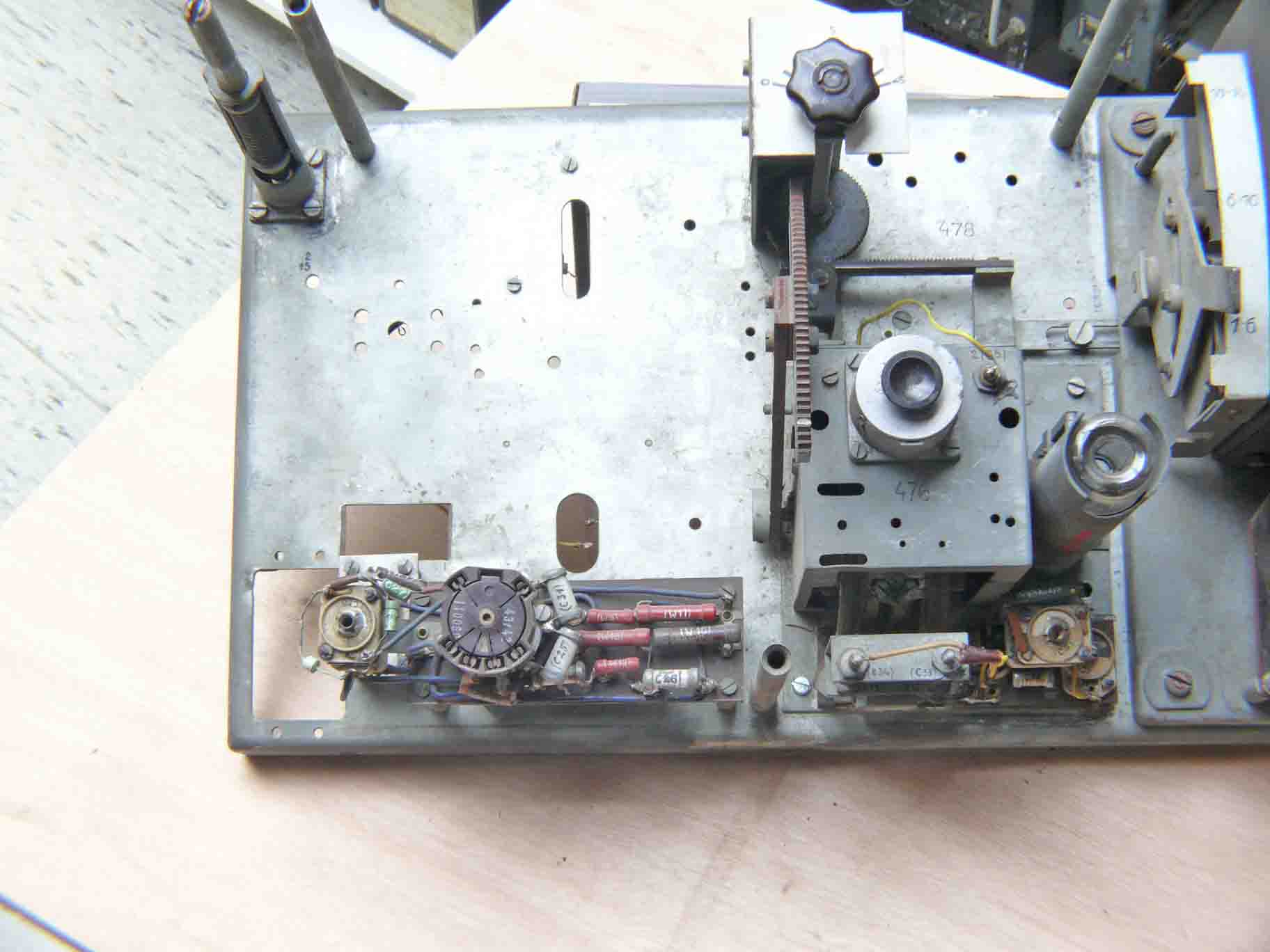
The chassis is now cleaned from unwanted components
Please notice that the chassis carries serial number 478. This might indicate that a series of at least say 500 units was ordered. The other option is, that it concerns module 478 (component). This might be indicated by the fact that the mixer module carries serial number 476. When we consider the 4 main modules: transmitter - mixer (476) - oscillator (450) - wave meter, which makes a total of 4 numbers, the figure must be divided by a factor of 4. In this situation, I guess, a total number of say 125 might have been produced (500 / 4). This latter number fits well with a figure given by Hoffmann-Heyden: of 125 Würzburgs being modified with the most advanced anti jamming techniques. A total of 100 sounds also very reasonable: 500 / 5 when the chassis frame is also constituting an essential module (making it 5 sections). Please bear in mind, that most of our Würzburg units are the ones discussed and photographed in Hoffmann-Heyden's book: Die Funk-Messgeräte der deutschen Flakartillerie (FAS III) 1938-1945, of about 1953

The two missing modules as we got them about twenty years ago
We may estimate that these were used as a signal generator. Who possessed in, say, early 1950s a signal source tuneable at 470 - 600 MHz? After dismantling the modules these were checked first and then mounted at their old places again. Who could ever have imagined that these modules would be reunited within the Urechse SÜ62d after about 60 years?

On the left the wave meter cavity, next the first local oscillator, left from the Nullode LG71 the mixer module, carrying serial number 476. The small adjustable potentiometer is for setting the sensitivity of the moving coil meter (fed from the cavity)
It is clear that the interconnecting wiring is on the rear side of the panel.
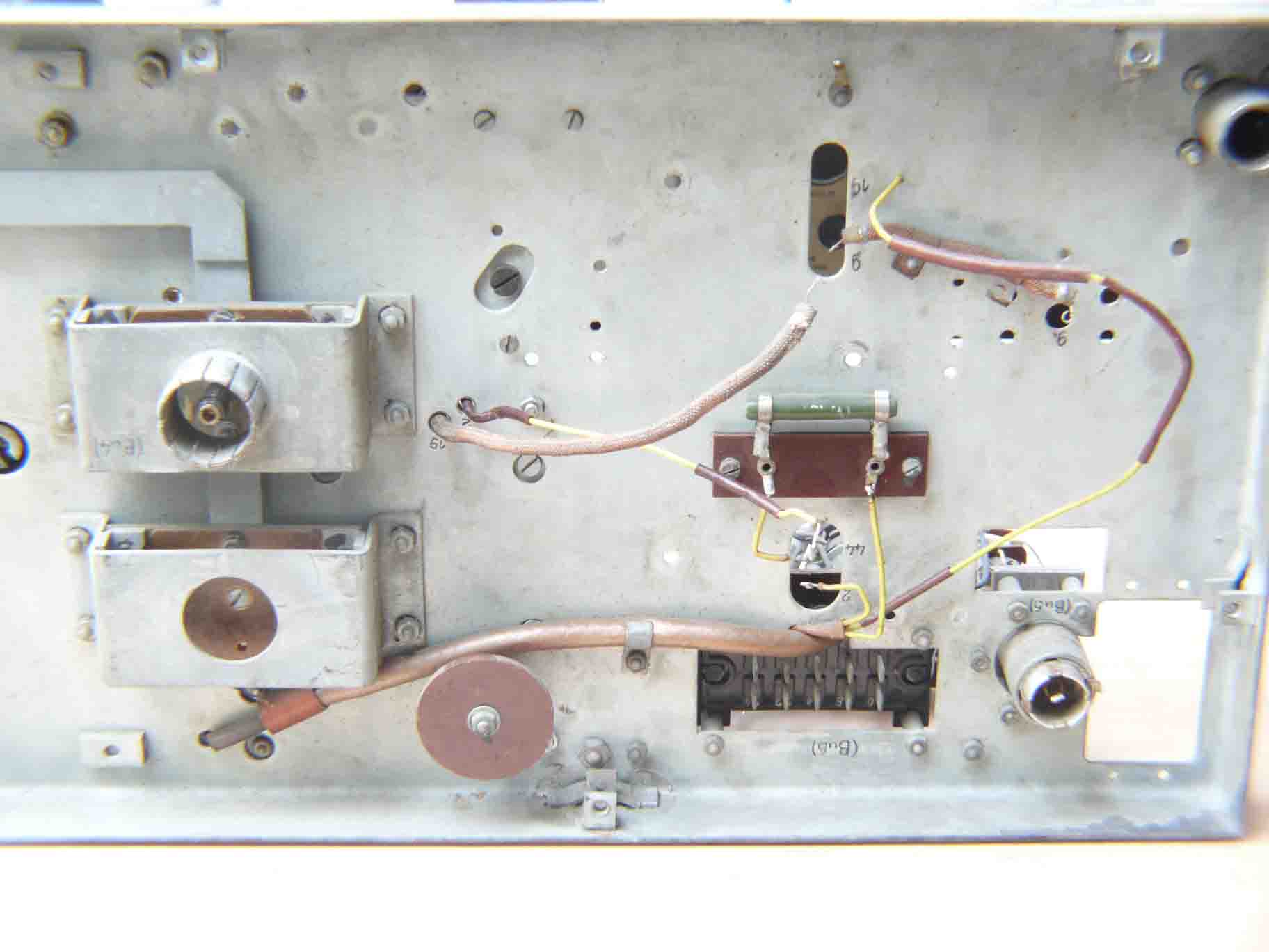
The situation inside the rear panel (the Michael module was already dismantled). For this occasion the rear cover plate had to be removed. The in- and output HF strip-lines are in between the main chassis and the outside covering plate. We may expect, that its line-impedance is controlled by their geometry and the free space between ground and the shielding cover plate

The wiring situation is restored as much as possible again
Next we dealt in detail with the first local oscillator.

Ü62d, the first local oscillator module
I first have removed the not original pick-up loop, which is replaced by a complete different type. But we are not yet convinced what form it finally should have

For convenience I have rotated the actual situation of the tuning system. With some imagination, we see that both the previous photo and schematic is representing the same situation. C 19 is a curious one, as it consists only of a single sheet of blue coloured pvc foil kept between the low end of the tuning coil and and chassis. Please look closely around the C19 marking and the bold heads at the previous photo. Its colour looks like some transformer insulation foil used for German transformers of late 1944. In those days German industry used pvc materials widely, particularly for high end applications. The length of the wire in between C19 and C44 is acting as a HF choke. Hoffmann-Heyden used for this occasion the symbol of a choke (however on the wrong side of the tuning coil)
When we now look again what Hoffmann-Heyden originally has drawn
We clearly notice, that this schematic is not fully identical. I guess that this was due to the fact that when the book and its schematics were made, the actual modules were already missing. He might have drawn them from memory
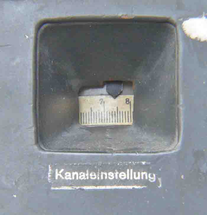
The receiver local oscillator frequency is checked by means of a wave meter cavity, which is calibrated in (channel?) numbers (the here indicated numbers are in between the red and blue sector). This was certainly done for security reasons. The transmitter course setting is also having numbers in this series. Red - Blue and Green sectors are particularly indicating the frequency band (spectrum) that should be employed. The lowest numbers match to the highest frequency (above red) up to about 600 MHz. The lowest frequency band (green) goes down to 470 MHz. This is not the actual transmitter frequency, though we have to subtract the IF frequency of 25 MHz. When thus the radar transmitter is tuned at 560 MHz the local oscillator is to be set at 560 - 25 = 535 MHz The lowest transmitter frequency possible is thus 470 + 25 = 495 MHz
I
During our continued work (13 January 2010) on the Urechse, I found that the existence of the cavity tuning is having a pronounced effect on the received signal level. It turned out, that when the cavity is detuned from the oscillator frequency, the received signal level is also becoming (very much) weaker. After some thoughts I came to the conclusion, that this is caused by the very high Q-factor of the cavity (< 1000). The output of the oscillator is linked by means of a capacitor of about 5 pF. This is constituting a not negligible impedance on say 560 MHz. The output loop of the oscillator is thus quite strongly coupled onto the cavity resonator and both are now interacting as being a (over) critical tuned band filter. Although the loop (link) inside the cavity is very small, having say about 5 mm in diameter (compared with the internal size of the cavity). That its influence is so much measurable is an unexpected phenomenon. There exist also a strong "pulling" effect of the cavity tuning and its measured output current. Tuning from a lower towards a higher frequency is showing a very strong resonance peak (there may be even two peaks). In contrast when tuning from a higher frequency downwards towards its apparent resonance point is not having this eminent effect on the indicated output current (indicating the actual level of existing energy inside the cavity). Thus, the higher the measured cavity energy is, the higher is the received signal.
J
Our next step is to improve the receiving chain sensitivity
(21 January 2010)
I removed first the IF module type ZFV 62 from its mounting frame and investigated it carefully.

The rear cover plate is removed and we notice the two coaxial wires running down from the two additionally attached coaxial connectors. The left cable is meant for the "Tastlaus" locking signal originating from module type E (see further down at section L). The right one is used for blocking the video signal when the IFF signal is presented at the coarse range CRT display (LB13/40). This so-called "Kennung B" is described in FuSE62 (FuMG62) Blatt H006 It has, however, to be noticed that the blocking pulse is not fed onto the last IFF stage housed in module J, but in our case inside module G (please notice also my further doubts and considerations at section L). This might originate from the necessity of not letting become the to be blocked IF signal too strong in the last IF stage. The overall amplification inside the ZFV 62 unit is about 200,000. The visible coaxial cables are probably made of pvc as, although their diameter is quite small, it apparently is soldered onto ground. Which can only be done with a soldering temperature of at least say 270° C.

ZFV62 front cover is removed. The modules A - F is shown. Modules G - J are just visible touching the table surface. The multi connector at the front is for testing: HT - gain control voltage and 12.6 V filament, with PV62 (Prüfvoltmeter). Please consider the ZFV62 schematic F003-2 shown more up this web page at section F

The yellow cable is linked onto the circuit of the local oscillator inside the IF chain. It brings the 25 MHz IF down to a value of 6.5 MHz. Consequently, the oscillator frequency is: 25 - 6.5 = 18.5 MHz. I first thought, that this coaxial cable is feeding the coherent locking signal onto this oscillator, as to allow the reception of Doppler modulated radar signals. This is apparently not the case. The 18.5 MHz signal must have been directly connected onto an outside circuit which is fed by a 6.3 MHz coherent "master" signal which was also adding both the 6.3 MHz master and the 18.5 MHz oscillator frequency as to get a 24.8 MHz signal. Please go for more details further down this page where we deal with both Würzlaus and the advanced Tastlaus at: section L

Again, the yellow cable coming from the left hand side, is conveying the blanking pulse for the interval that the IFF signal should be should solely on the coarse range screen. As this is done alternating at about 24 times per second, the observer is noticing two simultaneous kind of screen signals. See its basic principle shown below. Please notice also my later doubts whether it was not meant for feeding the 6.3 MHz 'master' signal onto the suppressor grid as to mix both the 6.3 and 6.5 MHz, which both will pass through the bandwidth of the IF stages H and J
K

The screen drawing may give an impression of what kind of screen signals the radar operator was looking at.
Next I looked inside all the different module whether I saw visible faults. Which wasn't the case. At the same time I used the opportunity to measure the parameters of the RV12P2000 valves. Three of them were having too low 'S' value and were replaced by new ones. After all was accomplished, I re-mounted the ZFV 62 module at its mounting frame. Sensitivity has improved considerably.

Next we look at a screen shot, which is showing Rehbock artificial target reflections up to 18.8 km. The first main pulse at a range of about 1 km is the actual transmitter signal. It is clear that this is not correlating with the necessity of that this should be at a distance of 0 km

The for us only relevant control is that of "Nullpunkt" in the deflection module A
Please bear in mind, that the circular deflection system used in the Würzburg coarse range CRT is based on series tuned deflection coils at resonance. When it is theoretically fed from a sinusoidal signal it will constitute an ultra linear circular time base (trace). This principle was invented in the early 1930s by Manfred von Ardenne.

After tuning the control "Nullpunkt" of the transmitting signal is now correctly set at 0 km distance. When we look carefully, we even can see the very weak signal reflection at 22.8 km
L
Würzlaus
(Wurzlaus)
How did it actually worked?
Although the word is quite well known, we may estimate that hardly people in the world actually know what it implies! Even a British report on aspects of Würzlaus did not grasp the principles fully. This was not the case with the more advanced Tastlaus system where full coherence was guarantied between all signal sources involved
Let us first consider the most simple system.

Coherent signal source type HS62/65 (Hilfssender). Number 62 and 65 indicate respectively that it is to be used for Würzburg 62D or for the Giant Würzburg type FuSE 65 (FuMG62 and 65). A ... D shows, that it is meant for the entire spectrum of Würzburg between say 580 and 490 MHz. The upper control is to adjust accurately the locking signal level onto the transmitter. The lower one is to set frequency

Inside view of HS62/65
The stable nature of the on the Michael oscillator based technology, should guarantee that its frequency deviation is kept small in respect to the Doppler spectrum involved. Please notice also my further considerations in the last paragraph of this section
To keep the implementation into military daily being, this locking oscillator was the only signal source employed!
Let us, for this occasion only deal with the most frequently used technology. Skipping all steps in between the very first attempts and the finally adopted technique.

The Regulierssender is equal to our HS62/65
One might ask now how does this constitute a coherent system? We must notice, that the coherent oscillator is tuned at a 200 kHz higher frequency and is pulling the transmitter pulses in the starting-up stage of the 1 (1.8) µs at a 200 kHz higher frequency than when the transmitter comes to its full transmitting energy. Its signal is jumping with profound coherent spectral lines. When the transmitter pulse is being in its switched off mode, the HS62/65 signal is still existing and will also be picked up by the receiver front-end. Be it that this carrier frequency is not in the centre of the IF bandwidth. This was done particularly as to prevent that the reflected target signals were becoming masked by the rather strong local signal. At the far end of the receiver chain the signal is detected and the now called video signal, containing both the target and the interfering local signal, which is having a beat tone of 200 kHz. Which is, however also being Doppler modulated when targets were having a radial velocity. The 200 kHz is becoming a dc component where the Doppler/video signal is passing through a low pass filter.
For more details please consider my book: Deckname Würzburg
For the next subject please consider pdf page 52 (my book page number 69)
You might remember, that our IF unit (ZFV62) has one coaxial connector linked onto the local oscillator of 18.5 MHz inside unit E. I don't fully understand how both match: our modified IF module might fit together with the far more advanced Tastlaus.
When we look now at the 18.5 MHz local oscillator and noticing that we only have a single coaxial signal connection, we might think that the 18.5 MHz signal was taken from this stage and being fed onto a mixer stage, which mixed the 18.5 and the 6.3 MHz master signal finally getting a gated 24.8 MHz coherent signal (unlike what is shown in this flow chart). This one was made by British post war investigators, which might not fully have understood the actual circuit details.
The mixer stage in which the 6.3 MHz master signal is actually mixed with the 6.5 MHz is causing some doubts, whether the blocking connector attached to our ZFV62 is only meant for blocking in case of "Kennung B" IFF, or that the coaxial line was getting the interfering 6.5 MHz master signal. Our IF unit is being marked by means of a red "K", which stands for Kennung. I am, however, not fully convinced that this cover originally belonged to our module. Two considerations one: the K on the IF housing and the coaxial connection which differs much from the described one in the upgrade instruction manual: FuSE62 (FuMG62) Blatt H006. As the IF signal originating from the IF module is fed onto the coarse range display ANG62, where it is in parallel split towards the fine range indicator EAG62. I consider, that both the fine range and the coarse range operators would like to know if they are looking at a Doppler or a non velocity modulated target. In this case it is most likely that the 6.3 MHz 'master' signal is connected onto the right connector attached to our IF module type ZFV62.
Comparing both the Würzlaus and the Tastlaus schematics, we notice that both created a beating interference video signal (200 kHz). The final cancellation took place at the CRT screen, where the relatively low frequency spectrum of the Doppler content was shown. The master cancellation took, however, place in the brains of the actual screen operator.
A spin-off of this survey is, that we might have found the solution to a point - that in the 1980s Alfred Price has raised about the fact that the 1st local oscillator inside the Urechse module was not connected (linked) onto the coherent and/or 'master' oscillator. Hoffmann-Heyden vehemently opposed this, with not valid arguments by the way. Both men were right and wrong. Please remember that I have discussed previously, that there occurs a capturing (pulling) phenomenon between the local oscillator and the attached wave meter cavity. Its very high Q-factor is interacting with the local oscillator signal and thus capturing its frequency behaviour in some respect. The purpose of the coherent signal in German radars was not to create an absolute value of measurement, but was only meant to keep the coherent signal deviation to be small against the actual Doppler spectrum in the time domain.
When one look at an actual (analogue) MTI signal on a oscilloscope, the Doppler signal is having a kind of "Butterfly" signature, which is constantly having fast changing patterns. Nowadays MTI and related technology is relying on FFT (Fast Fourier Transformations), which allows looking through chaff (window) clouds to a great extend.
M
On 2 February 2010 we continued our investigations
We have previously discussed the fact that the first local oscillator of the Urechse is not being straight forward phase-locked onto the central master oscillator at 6.3 MHz. The situation was different for the standard transmitter-receiver front-end type Eidechse (SÜ62c).

The yellow wire left of C13, running towards the Michael local oscillator module is to be used for the previously discussed coherent phase-locking of the oscillator circuit. C 13 represents the same pulse capacitor as was discussed in section B. On the far right we just see the transmitter module code-named 'Lokomotiv'. A + B + C means that the first local oscillator module allowed operation in the spectrum between, say, 570 - 525 MHz. Whereas the transmitter on the right could only be tuned in the spectrum of band A and B. What not always is fully understood, is that the Michael oscillator carried inside an additional tuning coil, which quite simply could be interchanged (by means of three screws). This operation might have taken, say, 15 to 20 minutes, in contrast to Urechse where it took about 20 to 30 seconds. However, it is thus not possible to tune directly between range 'A' up to 'C'!
The front panel of the Eidechse RX-TX. A + B indicate, that it could be operated in the ranges about 560 and 540 MHz. The holes in the wooden window is for setting and showing the actual receiver channel. The original Würzburg type A had an entirely flat front panel. Hence, the wooden window and the open section on the far right were additionally made, as to adapt for frequency change (known as 'Wismar' and for allowing phase locking of the transmitter signal)

From left to the right we see: The mixer stage - Michael local oscillator and the transmitter module called 'Lotomotiv'. German code-names are sometimes having a direct link with the shape of a device. In this case the module looks like a locomotive (Please regard its schematic in section D). The solid die cast frame box (housing) (Mg-Al alloy) is also good visible

We are looking now at the accessible cathode circuit. Its main function was meant for fine adjusting of the cathode circuit after frequency shift. Its second purpose might have been for injecting the coherent signal onto the transmitter as to allow coherent transmitter pulses. Please notice also the cathode tuning circuit of the Urechse in section B

The rear section of the Eidechse. This tube arrangement was called: 'Posaune' (trombone). Its function was: to match the asymmetric coaxial antenna line onto the symmetrical receiver mixer, but also to nullify the existing transmitter coaxial section (making it electrically invisible) during the receive interval (transmitter pause). The tube inlet on the left is meant for the air flow cooling

Official type number transfer, in 1941 the GAF started for security reasons with replacing their metal plates by 'water transfers'. Particularly after Operation Biting (Bruneval Raid of February 1942), where British parachutists brought home, among many other trophies, several metal type plates. German type plates give away a lot of fruitful information, in contrast to their British counterparts. For historians the German apparatus information is still most helpful. It is very simple to derive from German abbreviations the purpose of a device! The holes of the original metal plates are still visible. The square field down of 'Hersteller' might have carried: BOU*, which stands for Telefunken, but also could have originated from another firm, as Hersteller meant: those of whom actually manufacturing it (during wartime, modules were often produced even by competitive companies, what counted was only the ability to manufacture on demand and schedule as much as possible) * I am personally not entirely convinced that the Urechse design was from Telefunken. FAS III (Hoffmann-Heyden) or maybe "Köthen" might have been involved instead
Our next step was to investigate whether the power meter type Ln20978 to Würzburg (and Mainz, I guess also Mannheim) does work.
After having connected it onto the mains, nothing happened. I first opened the front panel:

The conical module on the left-hand side is containing the dummy load. The brass scale in the upper left section is attached to the wave meter cavity. On the left of it we just see the housing of the UHF diode SA 100. On top right of the cavity we see the housing of diode type SA102 to be used for power measurement
Nothing but an empty hole was visible. I considered that there might be a link between this empty hole and its not functioning. The right-hand module is mounted on a frame (equal to that of the Erstling IFF FuG 25a). After opening it I found a loose switch without wiring which certainly was put inside as to fake someone! According the manual a so-called "Kleinautomat" should have been used. I never have seen one and also never had expected one having a switching-off current of say 125 mA!
However, I found two cut-off wires and concluded that these can be connect onto a separate fuse-holder. The system started now to show some kind of response.

Let us now consider the front panel of the control module!
I wondered why the dummy load internal housing As 1 and W 1 is having such a particular shape. The total resistance of W 1 must be about 70 - 72 ohm. The impedance of a coaxial line is determined by means of the ratio D/d which must obey in free space being 3 (70 Ω). Regard now that 70 ohm is the resistance between the two far ends of the device. Let us regard now that in the middle of the resistance its remaining impedance towards ground is then 35 ohm. This means that the internal shape of the housing is (must be) such, that D/d (where d is constant due to the nature of the resistor) is designed that at each coaxial cross section D/d is matching to the remaining resistance towards ground. At the end of the line (ground level) D/d = 1.

When we consider both the previous schematic and looking at the principle circuit layout, we can see that something rather strange is happening. Instrument 'J1' should measure the current of the wave meter cavity diode, what it does in one position of the function switch U2. But its main function is, to control if there does not flow a compensating current in either way. Compensation is a principle that compares two voltages or current sources, when both are exactly equal then it is impossible that an equalising current can flow. Therefore a sensitive instrument is used having a central null (0) scale, like our instrument 'J1'. We will later see, that it actually works a bit different from what I just have explained. (Contradictions)
The next schematic is a bit difficult to find out what is happening with the various moving coil meters in the function modes.

Studying both schematics one might think that it was part of an April joke!
There exist a chain of faults and/or contradictions between schematics and the relating text. Compare, for instance, schematic 1 with the schematic above, and you will easily see that the wave meter never could have worked, as its anode is connected onto (0). I never encountered so many mistakes in a German wartime document! What might have been the case, is that the accompanied text and the schematic do not fully belong to each other, maybe owing to unnoticed modifications. As to determine how we can bring our power meter to function again, I have decided to add a special page, where we can determine step by step how it really should have worked. What also comes in mind, is that this schematic eventually had been drawn by a forced labour employee? Not unlikely, considering the actual date of week XV/44. (please consider also "Verloren Jaren" by Johan Kredit, dealing with his forced labour time in and around Berlin 1943-1945)
Let us investigate the contradictions in details (in progress)
O
4 February 2010
During my trials with the power meter I increased the output power of the Würzburg transmitter. At a certain point some kind of sparking happened inside the transmitter module, and its operation stopped at a certain point.
I remembered that already > 20 years ago there existed a tendency of some kind of sparking. The trouble is that the + 8 kV supply did not function any longer. After closer investigation I found that some relay contact or a safety relay was blocked inside power module NA II. (which proved later not to be the case)
I decided to eliminate the sparking fault first and removed the Urechse module from its mounting frame. Then investigated whether some burned part was visible, which wasn't the case. The next step was to remove the transmitter module from its main frame, as this was the only way to approach the HT cables inside the frame.

Transmitter module being removed (notice frame code 405825 which is a kind of production code)
The blue stamp (Lehrenhaltig) near to the rectangular free space is telling us: that all the chassis measures had been in accordance with the calibres.

The HT connector is removed and the HT cable is clearly visible. I had already decades ago put some extra rubber insulation in the hole as to prevent it from leakage. The next step is to replace these HT cables

The two HT cables are visible. The one for 8.3 kV is coming from the rear, the - 2.1 kV comes via the brown connector
We use for HT purpose so-called 'bobbin cables', which are used for motor bikes. It is not possible to use most car spark plug cables as these often possess an internal resistance, meant for suppressing the ignition noise
P
The next day (5 February 2010) I approached the problems again and first replaced the two HT cables. The second step, after having fit everything together again, was to find out why the 8.3 kV failed. What bothered me very much, was a modification which I had made about 1983/4. I had extra integrated a variac (actually being an auto-transformer, which is a transformer without secondary windings) as to be able to control the HT level of the 8.3 kV power supply (NA I). What I had lost was, that the input of the variac was fed directly from fuse Si 5, though, the output of the variac was then fed onto NA II (please notice section C) where it is controlled by R1 (current sensitive relay in series with the 350 V HT meant for the pulse-modulator. As to guarantee that the transmitter could not be switched-on without the grid blocking pulses of - 2.1 kV). It took me quite some time to discover that an internal fuse inside the variac was blown! After dismantling the variac transformer and replacement of the 2.5 A fuse, the Würzburg transmitter started luckily working again!
Q
On 5 March 2010 I have continued with arranging an experimental coaxial adapter between the Würzburg coaxial antenna cable and the power meter Ln20978.

Principle drawing of the coaxial adaptor between the coaxial antenna cable and the original power meter to Würzburg (Leistungsmesser). Drawing is not to scale. The inner conical conductor was machined in our mechanical workshop by our volunteer assistant Dick Zijlmans. D/d = 3 for 70 Ω is only valid when the spacing (dielectric) between the two conductors is air (ε = 1). The principle of bi-directional coupler is called "Richtkoppler" in German language
We tried to gain that the Würzburg antenna energy is being absorbed inside the power meter, which consist, as we have noticed in section N plus annex, of a power resistor of 70 Ω, a compensation circuit by which means it is possible to compare the amplitude of the transmitter pulses against a known dc voltage, and its actual frequency can be measured by means of a wave-meter-cavity arrangement.
The solution put in service is mainly meant as to show that our thoughts are indeed correct. It took some experiments before the shape and size of the bi-directional pickup loop was having its optimal (coupling) shape. This loop has a bi-directional function, as first it picks-up inductively the transmitter pulses and supplies this signal onto the Rehbock artificial target (by means of a coaxial cable). We have already seen that the Rehbock is responding delayed in time with a chain of artificial target reflections. Which signal is fed now onto the pickup loop and is inducing its energy onto the coaxial inner conductor. As Würzburg is now waiting for reflected target signals, it will also receive the induced signal from the artificial target Rehbock.

The Rehbock signals are clearly visible on the LB13/40 CRT screen. Even the third reflection is just visible (at about 13.8 km)
The weaker signal amplitude, especially in respect to the longer ranges, is also due to the not yet optimal signal transfer between the coaxial (conical) adapter and the Rehbock symmetrical antenna circuit. However, each Rehbock time delay window is, of course, having by its nature a lower signal amplitude.

Power meter Ln20978 is now showing that we operate at about 3.5 kW signal power output. The conical shape of our experimental coaxial adapter is just visible. Please compare the previous line drawing. As we have not yet made the actual coaxial connector, I have bridged the space between the adapter and the antenna cable by means of heavy copper 'litze' strips instead
The selector knob is set for power measurement (Leistungsmessung) and the moving coil meter J1 has just reached '0' level. Which means full compensation. It does not make sense to increase our signal power, as we do not radiate signals and we also do not use forced air cooling of the transmitter stage (LS180)!

For this occasion I have reduced the compensating voltage, thus the measuring bridge, represented by means of meter J1 is now showing that current is flowing towards the bridge-system. The previous photo was showing optimal balance (compensation). The meter deflection of J1 should, however, indicate a higher level (thus its pointer moving more to the left-hand side), due to the fact that push-button 'Komp' (Kompensation) is not being activated. This switch is better visible at the next photo. The reason for this is, that the meter (current) sensitivity is being reduced by means of a 300 kΩ resistor is series with the bridge-circuit, which switch should be activated during adjusting thepower value precisely

The test set Ln20978 is now set for wave-measurement (Welle)
The deflection of meter J1 is now only indicating the energy content inside the high-Q wave-meter-cavity (section N, current through diode Rö 1). The wave-meter-tuning is adjusted for optimal signal resonance. It is behaving like we have seen in the Urechse transmitter stage, where the cavity is showing a typical 'over-critical coupling' behaviour. Hence, one have to tune several times around a spot frequency as to pull-up the cavity onto its resonance maximum.
R
On 17 March we have continued our Würzburg survey project
Although, this time our attention is focussed mainly on adapting a tuning mechanism to the Urechse transmitter module. Its purpose is to make frequency tuning possible, as was also employed in the original Würzburg radars. Especially Urechse was relying on this kind of frequency control, because it covered all existing WB frequencies (Wismar-Insel A-D)

The empty hole a bit down right from the coaxial antenna connector is meant for the tuning mechanism. The brown single connector on the right is for the HT of the transmitter stage (max. 8.3 kV)

Shown is the major parts of the clutch mechanism. It is clear that one never knows what the actual angle of both clutch sections is (please notice its counter part inside the Urechse module, shown on the next photo). For this purpose, we have redesigned a mechanism to solve this task. The lathe work was done in our workshop by Dick Zijlmans. The 90° axial mechanism was an original German aircraft part (Winkelgetriebe). The entire tuning mechanism is our design, given the materials and mechanical parts available
The counter clutch section inside the Urechse module

Finally, we have fitted our complete tuning mechanism (tuning wheel on the far right)
Originally, tuning was done by the 'range and azimuth' operator, but frequency tuning is here to be accomplished on the right-hand side of the Urechse mounting frame. We have just used only original holes (maybe not always meant for its purpose, however, preventing damaging of the original mounting frame).

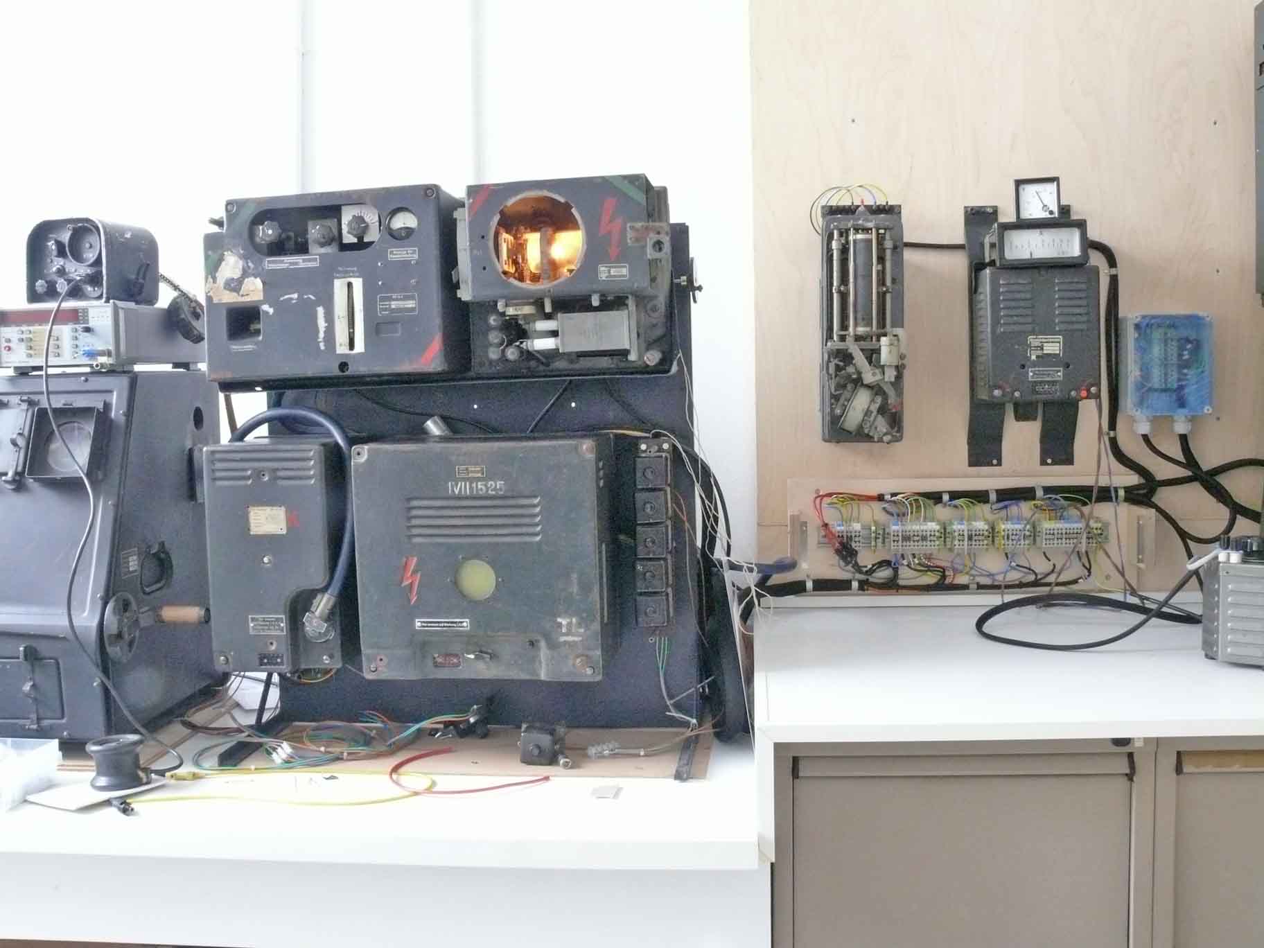
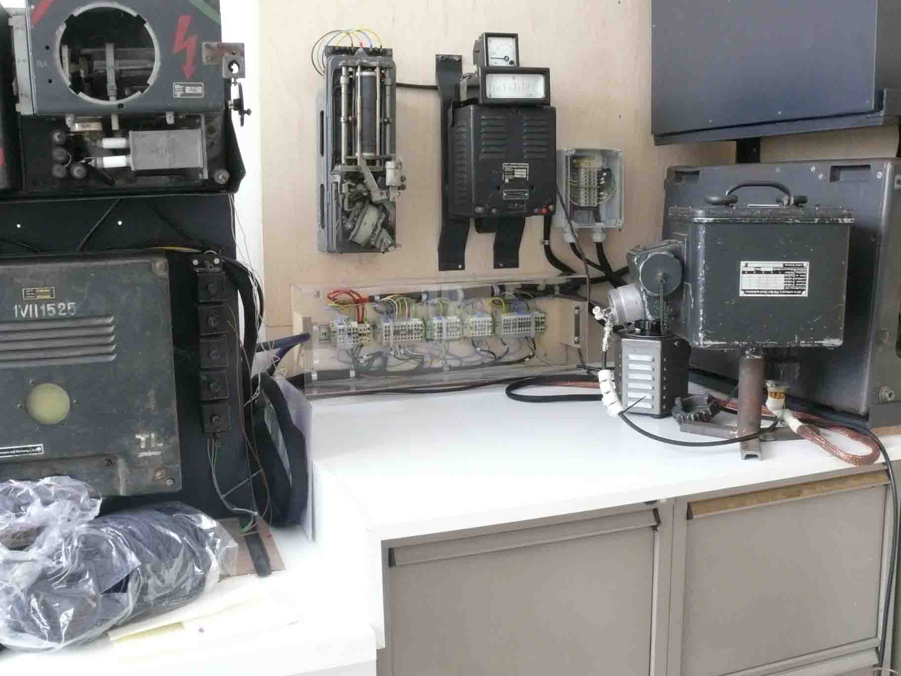
We have after about five months time (survey and repair) put the various units on their original place again. The actual blue coaxial antenna cable is visible on top of the power and frequency measuring set (Leistungsmesser Ln20978) (second module on the left). We still have to make the adapting coaxial connector between both the power meter (inside Ø 45 mm) and the existing coaxial Vacha type cable (inside the connector Ø 10 mm). Please consider the introduction of the previous section Q. Its front cover plate is still not yet fixed (mounted), as we will have a visiting group of the so-called "Radio Café" on Tuesday 23 March 2010. For the same reason we have not yet covered the main radar display unit type ANG62 again. On top of the digital counter (showing the actual LO frequency of the receiver) is temporarily placed the remote control unit of Rehbock. The meter at the far right on top of the power supply (representing NA I) is an electrostatic voltmeter for measuring up to 10 kV. The maximum HT employed for the Würzburg is 8.3 kV. In our situation we do not exceed say 6.5 kV

After we have put all the units on their intended place, we also have modified the coupling between the coaxial cable adapter on top of the power test set (Ln20978), discussed in the previous section Q and the Rehbock artificial target unit. We have also modified the coupling between the coaxial cable (Pope H125) and the symmetrical antenna input of the Rehbock apparatus. Two small Philips trimmers, having each say 4 to 5 pF were inserted, resulting in an increasing system sensitivity. Which is visible on the above screen shot. Even with strongly reduced receiver sensitivity, the fourth artificial target reflection (at 18 km) is still clearly visible
Section S
Please click here for a sound recording of the deflection noise, which frequency is 3750 Hz (MP 3). I have though to apologize for the quite high noise content, which is due to the "Dictaphone" like recorder. This recording will be renewed as soon as possible. When the audio does not work in your computer, please download the file at: http://www.cdvandt.org/WB-audio.mp3
Section T
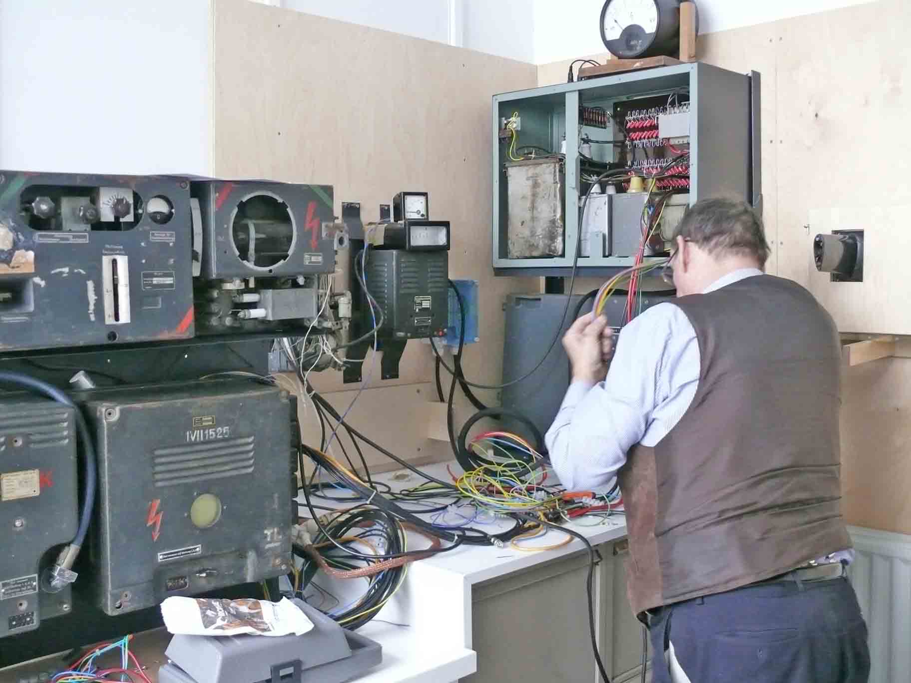
Dick Zijlmans has now started to redesign de wiring between the power supplies NA I - NA II - NA III as well as the the in- and output lines coming from the Würzburg radar itself. We have decided to make the interconnecting section in a logical manner. Thus, dividing the sections such that it is visible from which power module the wires come and also standardising the colours. Say, blue for 180 V regulated AC, maybe red for 350 V DC and so on.

Dick Zijlmans sorting out the existing and future interconnections
(photo with courtesy of Reinhard Neuteufel from Vienna, 2 June 2010)
Section U
In February 2011 we have resumed the work on our Wurzburg (Würzburg) apparatus.
Dick Zijlmans has drawn the schematic as to how we can logically interconnect the wiring between the power side and the Wurzburg radar system. It is our intension to bring this project to its conclusion; as we would like to focus our attention to other museum projects.

This interconnecting section is linking the NA I and NA II power supplies onto the Wurzburg system (Gestell) wiring
This section (Schnittstelle) is interconnecting the NA III and the Pintsch-Regler onto the 'Gestell' wiring.
Dick Zijlmans decided that it should be done in state of the art technology. Although, nowadays for practical reason screws are rejected as to speed up wiring, we have decided to use the screwing technology.
Continued with section V
On 9 March Dick Zijlsmans resumed his work on the interconnections between our Würzburg power supplies and the radar system
Dick Zijlmans' first concern is to replace the existing wiring between NA I and the central interconnections

Inside the box you can see the state of the art way in which Dick Zijlmans is thinking. That the photo is a bit fuzzy is due to the not yet removed blue plastic covering sheet
Section W
On 27 April 2011 Dick Zijlmans has continued his work on the interconnections between the power-side and the consumer side, constituted by the so-called: Gestell, which is the apparatus frame

Dick Zijlmans has mounted the interconnecting strip, for the occasion of preparing rewiring, on a wooden plank. Please notice the wooden frame mounted on the wall just next to the bundle of wires, that is the place where the rail ultimately will be fixed, covered by means of a transparent Perpex (Plexiglas) cover
But, delivering sound cabling it is convenient having the cables in front of you. The mash of cables will be cleaned up when all wires are being interconnected. The black nylon hose is bundling the wires

All interconnecting (made by Weidmüller Germany) strips are soundly mounted onto a rail

For this occasion it is helpful that we can rely on a good cable-plan (wiring schematic)
We have grouped them in a way so that each section is handling a separate power source. When appropriate, extra interconnections are being made between the sections.

The yellow/green interconnections are handling ground, and are being grounded onto the mounting rail at certain points only
The cable on the left is going towards the apparatus frame. Dick hasn't yet connected the power supply side, as we otherwise would no longer see the wire-mash in the background!
On 18 May Dick continued his rewiring work

Comparing the previous photos, it is evident that he made much progress
The contact rail is mounted on its final position. The output side being ready and the next move has to be the input side. The fact that Dick removed all old contact blocks, relying now fully on the correctness of the wire colours. But this is the way it should be done by a cabling expert as he is!
Dick Zijlmans continued his cabling work on 25 May 2011
This may be regarded his final spurt

Preconditions for his final wiring

Dick's wiring is nearly completed
Some wires have to be modified, like the ones for the Amp-meter and the 180 V stabilised AC indications, as well as the still missing 6 mm interconnections. After completion a Plexiglas (perspex) cover is to be placed finally for protection.
The Würzburg apparatus is working again
HF power was indicated by means of a neon bulb. Whether the artificial target Rehbock is still working has to be checked next week. The square meter is indicating the stabilised 180 V AC the flat one is indicating the current consumption. The RF energy is always being absorbed in the power meter (Leistungsmesser).
The cable work has nearly been brought to its conclusion and the safety perspex (plexiglas) cover is being placed
Some small modifications has to be carried out. For instance, connecting a more adequate power cable between the NT62 and the interconnection strip. Later, when we have found a new 'moving iron'instrument, the temporary wiring has also to modified.
Section X
A next project is to involve the rotation of the antenna motor with a double target diplay in for the elevation and azimuth bearing scopes.

The antenna motor has been removed from its waal mounting
As to rewire it

Dick Zijlmans is modifying the interconnects
The small crt at the ANG62 display unit is the scope for controlling accurate antenna azimuth

Schematic of the antenna motor DA62

Examples from my book on Würzburg
The operator's aim is to keep both target signals for each crt scope at equal amplitude.

On 22 June Dick Zijlmans might have connected the final mains power cable.
Interconnecting NT62, the WB original mains transformer, and the central wiring section. Covered now by means of a Perspex (Plexiglas) transparent cover. This power cable is visible on the far right.
To be continued with section Y
Discussion and coments:
* Henk Peek sent me recently (30 December 2009) his following e-mail comment:
De weerstand van 16K par. met de condensator va 0.05uF is de protektie van de LS180. Als de dutycycle de mist in gaat of het negatief valt weg dan beschermen deze weerstanden de lS180. Gedurende de puls van 1 us wordt de condensator 40V opgeladen. de weerstand van 16K ontlaad de condensator continu en daar staat gemiddled 96V gelijkspanning over met een rimpel van 40V. Alleen als het fout gaat loopt de spanning enorm op. De weerstanden van 16 K zijn waarschijnlijk ook thermisch beveiligd.
My replay in Dutch language:
Dag Henk,
Bedankt voor je commentaar!
De echte pulsstroom of anodestroom van ongeveer 2 A (uitgaande van een uiteindelijk rendement van zeg 50 %) kan alleen door de condensator geleverd worden. Dat er alleen stroom geleverd kan worden m.b.v. een min of meer ontladen C is, volgens mij, de enige verklaring van het geheel. Het is bekend dat de output aan de antenne gemeten ongeveer 8 kW is. Dus de pulsinput zal ergens tussen 12 à 16 kW gelegen moeten hebben. Klasse C geeft, als ik mij dit goed herinner, theoretisch 70 % (77%?) rendement. Je hebt natuurlijk gelijk, dat de parallelweerstanden ook een beveiliging functie hebben. Er kan echter bij zeg 8 kV en een weerstand van 16 kΩ maar 0,5 A lopen. Deze stroom moet dus eigenlijk van de ongeveer 2 A worden afgetrokken. Het zijn echter duidelijk draadgewonden weerstanden en die hebben een niet te verwaarlozen eigen zelfinductie, die zeker bij pulsen <2 µs een zeer negatieve rol gaan spelen de pulsvorm bevat toch een spectrum tot 10-7.
Ik neem echter aan, dat als er 4 kW continue opgenomen wordt, dat de betreffende zekeringautomaat uiteindelijk zal uitschakelen (dat zou het resultaat zijn van het continue opgenomen vermogen)! De anodedissipatie van een LS180 is maar 180 W.
De vier vermogensweerstanden in serie zijn behoorlijk zwaar en vermoedelijk gefabriceerd door Rosenthal. Ze zijn echter niet thermisch beveiligd. Dat er een rimpel aanwezig is is evident. Dat kan niet anders met een puls-pauze verhouding van 1 : 333.
Henk Peek has much experience with high power pulsed systems, as he had worked on 10 MW klystron generators!
Arthur O. Bauer
Please don't forget, to click on most of the illustrations, as to get the best screen reproduction quality. (or simply copy it by means of Ctr+C and paste in into a document by means of Ctr+V)(Window PC)
On 20 March 2013
After a quite long delay new progress have been made in bringing our Würzburg Repair project to a conclusion.
One of our major concerns was making an appropriate coupler which fits onto a German coaxial connector and the Leistungsmesser (power meter) of our Würzburg system.
The hampering problem was finding someone who is capable and more significant will to assist us. This bi-directional coupler is of our own design, as we would like to link the WB signal onto the range-test-transponder Rehbock. For it we have to pick up a small amount of energy and sending the pulses time-delayed back onto the coupler and from there further onto the front-end of the SÜ 62d receiver. Experimentally it worked, but it called for a final sound realisation.

Jaap Keijzer firstly fitted an original coaxial connector onto the very nice Vacha cable. I have to admit, that this connector was originally meant for the Liechtenstein SN2, but was the only connector available
Showing the way both the coaxial cable and the coaxial couple will be fit together
For some of you astonishing, this connector type may be regarded the basic idea behind the nowadays famous F-connector. As the coaxial core is acting as pin + contact-conductor.

Fitting the coaxial connector onto the bi-directional coupler

Some of you may wonder why its shape is conical. The reason is quite simple: The impedance of a coaxial cable (in air) is dependant on the ratio between the D/d where d is the diameter of the inner coaxial conductor. For 70 ohms the ratio is 3 Thus an impedance will be staying equal as long as at any instant a system is obeying to this law.
Viewing finally the coupler-link
On 6/8 April 2013
Today I would like to operate the Würzburg system which is on display in our museum. Jaap Keijzer has finally made a working version. The coaxial cable connector being fit onto the bi-directional coupler.

The Vacha cable being connected onto the bi-directional coupler, which is screwed on top of the 70 ohm dummy load
The BNC connection on its side is the two connection onto the artificial target Rehbock.
I also used the opportunity to make 9 YouTube films, showing various aspects of the Würzburg main screen (LB13/40) which is covering the range between 0 and 40 km.
Film 88: Viewing the Würzburg wide range screen (0 - 40 km), the artificial targets being visible. Also some fine tuning is done, as to get an optimal match between TX and RX frequencies versus the local oscillator of the artificial target Rehbock. The high pitch you hear all the time originate from the Würzburg PRF, which actually is 3750 Hz. The reason that it can be heard is being caused by the Magnetic deflection of the LB13/40 CRT, maybe also caused a bit by the range goniometers. (00082)
Film 89: Viewing again the LB13/40 measuring screen, looking also at the LB1/LB8 CRT which shows currently the range just below 10,000 metres, on itself it covers a spectrum of 5 km. You should see two pulses allowing accurate pointing the antenna centre at a target in the azimuth plane owing to conical scan. We are not yet having made a simulation which is to be fed from (by) the rotating DA62 antenna. (00083)
Film 90: Jaap Keijzer has now kindly finished the construction of a bi-directional coupler. The Würzburg signal is being absorbed inside a dummy load (power meter). Power is causing a current flow in the core of the coaxial cable; this current is causing a magnetic flux around it, which is inducing a current in a small closed wire. The induced current is being fed via a coaxial cable onto the artificial target Rehbock. Rehbock is receiving the signal and the transponder glass-line device is sending delayed pulses towards the Rehbock mixer again. This mixer signal is also available at the circular polarized Rehbock antenna and being received thereafter by the spinning Würzburg antenna (in our situation inductively inducing a current in the core of the coaxial cable again, which current flows now into the direction of the Würzburg receiver again). (00072)
Film 91: Viewing the Würzburg Transmitter / Receiver front/end called Urechse (SÜ 62d). This apparatus is very rare, it is designed for allowing fast tuning of the Würzburg operational frequency; as a result of increasing Allied jamming was it found necessary to introduce fast tuning abilities. However, the wartime circumstances of 1944 did not allow its large scale implementation. According information, setting took about 20 sec. only. In contrast, the regular Eidechse SÜ 62 b or c took at least 45 minutes! The screening window of the transmitter being removed. On the left-hand side we see the receiver section. The controls from right to the left are: wave-meter tuning indicator, the tuning of the TR matching versus the operated frequency. Followed by the local oscillator tuning. On the far left the tuning of the wave meter; where its optimal tuning versus the LO tuning is being indicated on the moving coil meter. More on the right, we see the Pintsch Regler, known in England as a 'carbon pile' regulator. A special magnetically controlled arrangement is pressing or depressing the carbon rings such that the current output voltage is being kept at 180 V ac. Constituting a quick responding variable resistor, which is reducing 220 V into a stabilised 180 V ac. (00073)
Film 92: Viewing the modern interconnections of our Würzburg system. Dick Zijlmans made it some years ago. It looks proper. The way the cables are being interconnected differ from the wartime plans, as functionality is what counts now; like all HT connections concentrated in a single block section. (00074)
Film 93: Viewing the Pintsch Regler, the hum is originating from the very fast response of the voltage regulator, thus following our 50 Hz mains frequency. What we hear is a kind of resonance, where action and reaction is constantly interacting (a kind of fast hunting). This phenomenon can sometimes be interrupted by only damping its fast vibrations. (00075)
Film 94: Viewing the Rehbock artificial target unit more in details. (00076)
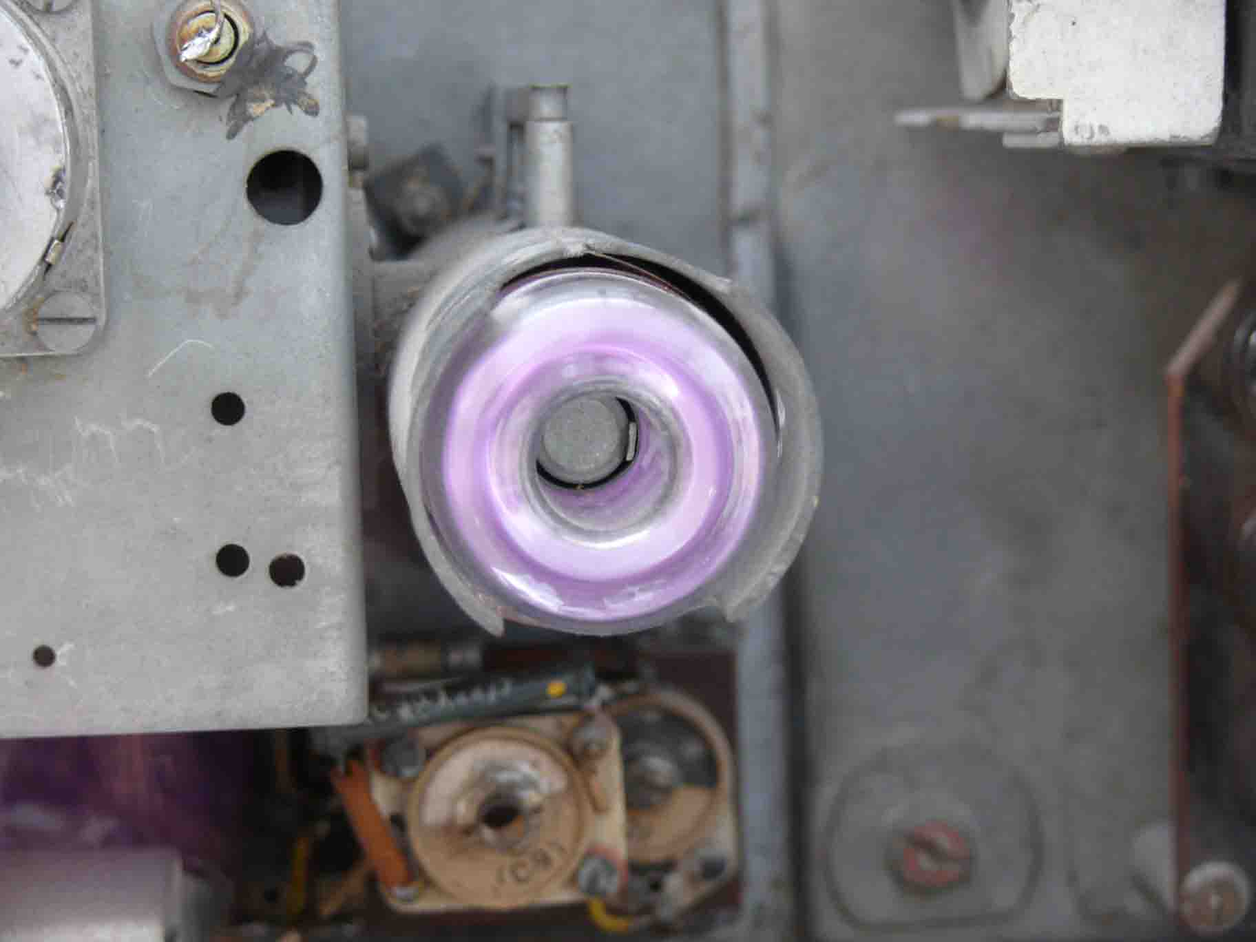
Film 95: Viewing the SÜ 62d transmitter in the background we see the bright glow of the LS180 filament. A neon bulb is proving that HF is present. Please remember, that the high pitch tone is being caused by the 3750 Hz PRF and is originating from the ANG62 main screen (LB13/40) magnetic deflection yokes, maybe less from the range goniometers. At 3750 Hz locating (aural DFing) the actual origin of the high pitch (tone) is hardly possible. (00077)
Film 96: Viewing the power meter type Ln20978 of the Würzburg system. (00081)
On 28 May 2013
Time has come to investigate what goes wrong inside the Leistungsmesser Ln 20978
Viewing the fact that this particular page is extremely heavy loaded, it is decided to create a new one only dedicated to increasing the performance of the Würzburg system in conjunction with the Ln 20978 power meter and the Rehbock artificial target.
Please continue with the new dedicated web page
To be continued in due course
Please consider also our contribution on: Aspects of German radar calibration
Go back to, or proceed with: Mr Opitz's Würzburg system model
Go back to: Exhibits new
![]()