
MZSS
The power supply to the SCHREIBMAX
The Enigma Schlüssel M4 printer
The Schreibmax MZSE survey
State of affairs: 2 December 2010
Power supply front side open
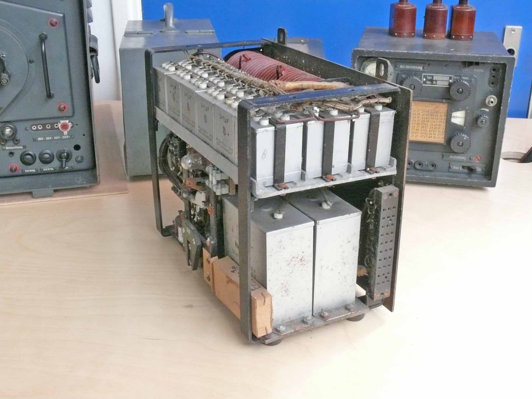
MZSS power supply right hand site
Please notice the 30 pin connector which links this very complicated apparatus onto the Schreibmax printer unit. Each alphabetic character is having is own discharging capacitor, which is being discharged by means of a hammer mechanism that strikes the paper tape from below and is pressing it onto the revolving lettering wheel. This is necessary as to prevent that another character could be activated as well. As our alphabet is having 26 characters + one power line is necessary for the rotating motor mechanism one needs 26 + 1 + earth at least 28 inter connecting wires. Maybe the motor system may need even two or more inter connections.

Shown is the contact block of the Schreibmax text printer (notice the b/w photos down this page)
Please notice the connecting cable between the MZSS power supply and the Enigma printer
On 19 November 2010 we have started with investigating the technical aspects of this rather complicated MZSS power supply. Owing to the lack of appropriate documentation (handbook or manual) we have decided to connect the power supply onto the local mains (230 V) via our standard protection arrangement incorporating a light bulb of say 40 watts, which is being short circuit (a parallel switch onto the light bulb) when we trust the mains current of the MZSS (mains) loading. The first difficulty we encountered was the fact that the mains power switch was broken already before we got it. It was, however, possible to get some dc voltage on the two in series connected electrolytic capacitors, by holding the mains relay (switch) in a certain position by means of a screwdriver. To investigate the so-called 'automatic-fuse-switch' it was necessary to dislocate it. The only way to access it was to remove first the two electrolytic capacitor blocks. This power supply apparatus was delivered in according most date stamps, wome might indicate that something was done in 1944 as well.

The MZSS power supply unit with the two electrolytic capacitors (2 x 750 µF in series, constituting 375 µF at 2 x 100 V = 200 V dc) on the right hand side already being removed. In the centre we see the empty space where the automatic-fuse-switch was mounted. Please notice in the previous photos the shape of the two electrolytic capacitor blocks. Measuring their capacity it is found that both had lost most of their capacitance. To keep the power unit as original as possible, we will leave them in place, though, have to bridge them by means of 4 modern tubular electrolytic capacitors. It has become our policy to leave block capacitors as they are, thus not opening them. Some collectors will put new capacitors inside the opened can. In my perception this is wrong doing, as in a matter of time these replaced electrolytic capacitors will also suffer from altering deviations. What is appropriate is, to bridge the block capacitors by modern state of the art ones. These are in most cases smaller and the available free space is sufficient to keep them without problems. The only problem encountered might be that paper capacitors of the 1940s and nowadays types might not differ much in their actual size. Especially for the high voltage types such as for types passing 500/750 V. When the time comes that it is no longer appropriate to switch on electrically an artefact, the bridged components can simply be removed and the genuine state of affairs is being restored. Only the difference in brightness of a soldering is then indicating that it once had been touched!

The automatic-fuse-switch arrangement
Its purpose is, that when the mains current, for what ever reason, is passing a certain level the switch arrangement is released in the off position. The coil in the centre is connected in series with the mains power and will act upon on a too high current level. The blue/gray mounting-base consist of ceramic

The same switch shown from a different perspective. The centre bobbin (one of out of two) is also part of the current sensitive relay arrangement
It is clear that the Bakelite handle is broken. Our next move is to repair it by means of a substitute arrangement.

The first step undertaken was to repair the missing lever
This was accomplished by first removing a piece of broken wood. It was found that the diameter of the remaining hole was about 3.6 mm, which is appropriate to fit a 4 mm threat in it. The second step was, to drill a hole in a brass rod of 4.3 mm. Then drilling a bigger hole in such, that the screw head was kept a few deep. The screw head was on our lathe reduced in diameter up to about 6.4 mm. The lowest end of the brass tube was shaped such that it fitted well onto the shape of the Bakelite holder (on the photo looking black)
The next step was finding out about both the MZSS power supply and the Schreibmax MZSE circuitry. It proved to be a most complicated system. It was curiously discovered that two wires of the 30 pin connector between the MZSS and MZSE was carrying 220 V mains directly! I could see that some of the related wires had been changed. I guess, that the 220 V ac was originally coming from the mains transformer. A voltage selector allowed between 75 V and 220 V ac mains supply. For what ever reason, someone has modified this into a quite dangerous wiring. It was secondly found, that our 30 pin connector cable was only having 20 wires being used. We luckily have a full wired cable which is being used to interconnect the WT 40 system (multi channel telex FSK interface).
The main voltage coming from the MZSS power unit is about 115 V dc. After I had interconnected both modules (MZSS and MZSE-Schreibmax) no warning buzzer was signalling that something was wrong. What ever effort was being put in, the Schreibmax printer wasn't responding at all. Desperately I searched Google, what I found was most disappointing (frustrating). No manual; and some sources were quoting from our website without giving reference. What was most irritating was - that some called it a "simple" printer being attached onto the Enigma. Please believe me, it is everything but simple!! ('NIX' simple!!) It is a very most complicated device. It is always quite frustrating working on systems where there apparently doesn't exist schematics or any relevant reference and/or information. Only my good old friend Fritz Deters from Bremen, he told me recently, in contrast to which I thought, that the machine runs and stops and then starts again. He proved to be still right after at least 65 years! But as a wireless operator he knew nothing about its internal technique. He was not supposed to open it!
Like in my Würzburg-Rep! survey, I was again trapped in the curious implications of a R and C circuitry. My experience with the Siemens G-Schreiber T52d where a capacitor was used to trigger a printing hammer such, that the paper was touching the rotating text-wheel just at the appropriate interval pointed me into the wrong direction. The arrangement of 27 x 1 µF high quality hermetically sealed-off capacitors of 1000 V type confused me seriously. Why 27 capacitors which were apparently all being fed via a separate 1.5 kohm resistor. What is more likely, than that the stored voltage is being used as to activate some mechanism?
However, it took me some days of consideration before some of the found implication was attracting my attention.
The arrangement of 27 x 1 µF is visible in the upper section of the MZSS unit
After I had realised that 220 V ac was being fed onto the Schreibmax, I firstly focussed my attention onto the motor mechanism.

This photo shows the rear side of the Schreibmax apparatus (bearing-plate being removed)
When I first had fed 220 V ac onto the central driving motor of the Schreibmax, nothing happened. After a while the motor started to respond minimally. My first thought was, oh lubrication has to be done. I took off the rear bearing-plate and the bearing balls were being kept within a tiny steel frame. The bearing construction clearly was designed as to centre its system. After I have greased it, the rear bearing plate was mounted at its appropriate place again. The other bearings are nevertheless very difficult to be reached as in this case the entire mechanism had to be dismantled. Because we have no mechanical construction drawings, I decided to drip some oil into the bearing also using gravity as to penetrate it. However, all runs now smoothly. Lubrication is certainly a point of our attention when this survey has been accomplished.
The circular heavy device in the centre of this photo might function as a flywheel maybe also acting as a kind of friction clutch. What is actually the function of the strange tubes arrangement?

You might have already noticed, that a spare box is attached between the heavy electrolytic capacitor block and the main frame of the MZSS module
Why does it contain components that doesn't fit into the power supply? It is clear that these belong to the Schreibmax printer. Please consider the previous photo and you might see acquaintance between the lowest shown spare part and the circularly arranged tube like devices. Towards us is visible the character N which points to one side of a magnetic device (maybe not quite visible on this photo).
When I turned my attention towards the magnetic mechanism and was asking myself what its function might have been; still nothing happened, even when I connected the full HT of 115 V dc onto a single electromagnetic device.
What goes wrong?
After some extra considerations even having some sleepless nights, I wondered where the next shown spring loaded arrangement is being meant for?

I discovered that it was only indirectly part of the magnetic controlled arrangement
It proved that all the brass rods where owing to stick grease (remember > 65 years old!) being prevented from responding onto the movement (impulses) of the electromagnets. First it was thus necessary to make each of the 27 spring-loaded rods movable again. Some were rather difficult to reach.
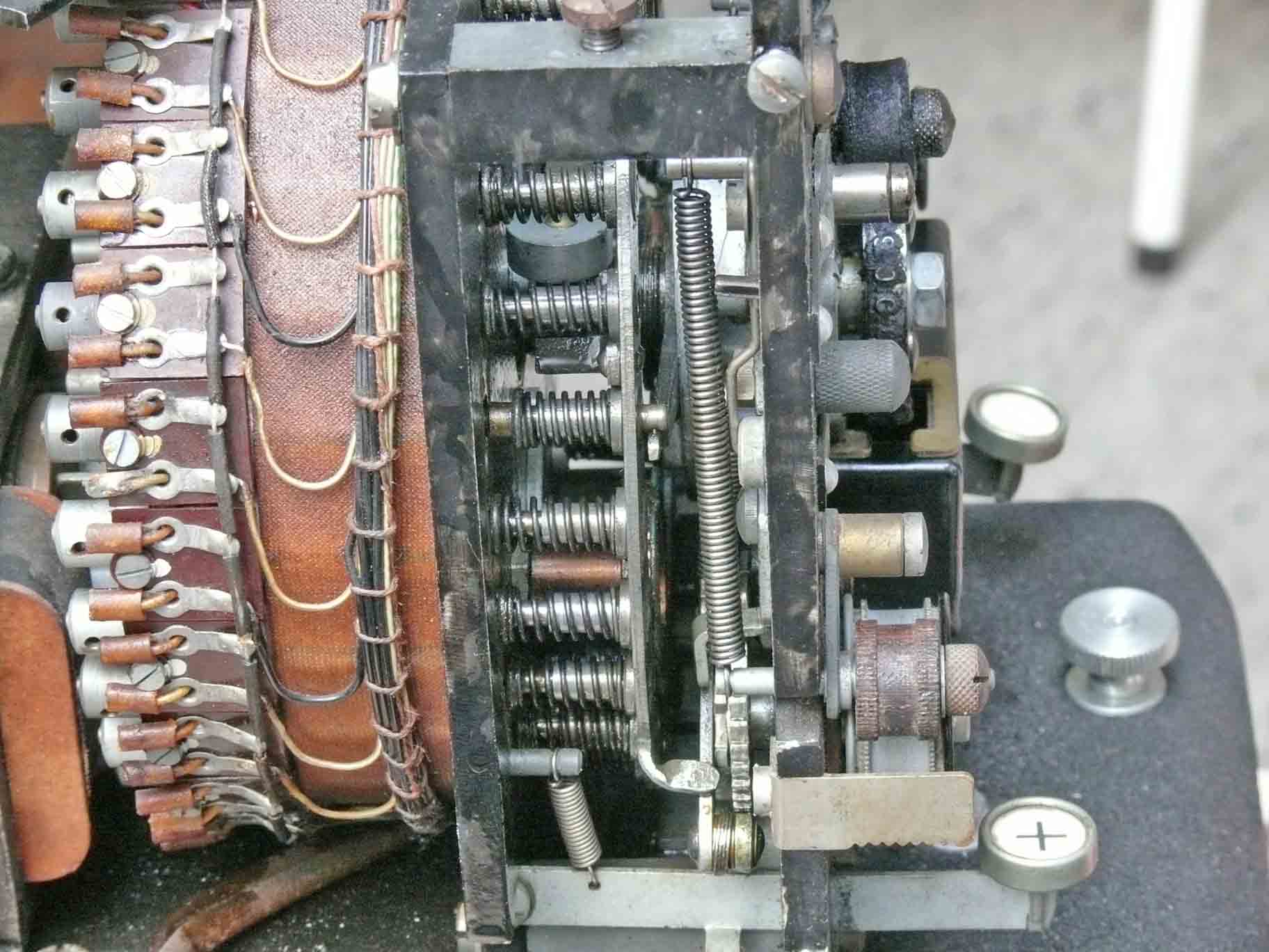
Please look at the ejected brass pin and the grey/blue metal finger just touching it
How does it work? When an electromagnet is being activated by means of the Enigma machine, one out of 26 is being ejected. As long as this doesn't occur the central shaft is rotating constantly. On the main shaft is mounted a long flat steel finger-strip. When a certain character is being activated inside the Enigma apparatus, the according pin is being ejected (activated). The quite fast rotating central finger arrangement is rotating until it is being hold (stopped) by means of the ejected brass pin. This will cause a mechanical impulse. What I haven't yet discussed is, that the spring loaded metal plate is mounted such, that it can also rotate about 10 degrees clockwise. In fact, it is relieving the mechanical momentum of the stopping mechanism, by absorbing the energy (stopping force) two things happen: first the hammer mechanism is being activated so that it struck for a short interval the paper tape onto the inked text wheel. Please try to recognise this wheel, where some characters are just visible. The second function is, of course, also a relevant one - as it is activating paper tape movement for a few mm, just after a character had been printed. The blue coloured felt ring is for supplying fresh ink onto the printer wheel (Schreibrad).

The stopping prossess shown schematically

My screwdriver is pointing at the printer hammer, which hits the paper from below only for a rather short period. The printer text wheel is also clearly visible. The paper transport wheel with the 5 white dots on it, just above the + key button, is meant for transporting the paper tape. Its stepping mechanism is being activated each time the spring loaded arrangement is rotating about 10 degrees forwards and backwards again
We have already noticed, that we have an arrangement of 27 capacitors together with 27 magnets. But, the West-European alphabet is only having 26 characters. The solution is found in viewing the previous photo. The key '+' is the answer. It activates printing the character +, without touching an Enigma M4 key. The key on the right hand side is a so-called blank key, which is only activating paper-tape-transportation, without printing a symbol. This is done by mechanically forcing the spring loaded arrangement to rotate about 10 degrees clockwise and then backwards of course.
Most of the electrical circuit is not very difficult to understand

In my opinion quite curious is the fact that the lower sides of the 1 µF capacitors is interconnected between them only; it does not have a connection onto the rest of the circuitry. One may regard that it is "floating" (the cyan coloured wires). The system still does work when the "floating" section is being connected onto the negative pole of the power supply. But, this will cause damage to the Enigma switching contacts, as it will be discharged by means of the enigma keying contacts. Short circuiting a capacitor which is being charged up to 115 V at once, is causing a relative high current as its stored energy is: J = ½ CU² = 1.10-6 x 115² = 0.0066 Joule (neglecting the additional current through the magnet coil and the parallel resistor as well as the so-called reverse voltage originating from the interrupted magnetic flux of the magnet-coil). This may cause contact damage in the long run. During my experiments, when I had to trigger a contact manually, quite some sparks were seen. I guess, that the 1 µF capacitors are interacting as a damping network in combination with the inductances of the remaining 26 magnets as well as in combination with the 27 x 1.5 kΩ resistors parallel onto the electromagnets. The quality of these 1 µF capacitors maybe having an important function, as the used types are meant for 1000 V; and being of the so-called hermetically sealed-off types (guaranteeing a very long life cycle even good after minimally 65 years have been passed)! Nowadays one would use anti-parallel connected diodes instead. Although I cannot prove it, the HT voltage of 115 V dc might be a compromise as to limit unnecessary Enigma contacts loading. I have discussed this curious circuit with my friend Joop van Bree during a rather long telephone conversation (28 November 2010). In the prephase of my problem he directly interrupted me and said: I know this circuitry it is called "Snubber Schakeling". 'Snubber circuit' is thus the name. He also mentioned, that it is still an actual technique when very high power thyristors are involved. As diodes are not adequate enough damping the high anti-pulses owing to circuit inductance.
By clicking on the drawing you can open it in your PC directly
So far non of the shown pictures gave us its full principle

Simplified drawing of the Schreibmax mechanism
Please click on the line drawing as to open it in your own computer
On 1 December I have tested whether my assumption is justified that the above pointed device FW/C is truly a flywheel-clutch. I marked both the outside cylinder and the (inside spring loaded) dark brown pertinax back-plate (please notice the photo with the driving motor). After I forced the Schreibmax machine to print one or two characters the flywheel markers had moved against one another. This friction clutch is thus absorbing the system-inertia.
Let us continue now with the way the Schreibmax is mounted on top of a U-boat Enigma type M4

The contact block of the Schreibmax printer is to be contact the electrical circuit of the Enigma M4 machine. Instead of small lamps the Schreibmax printer is getting a electrical signal which is can be printed on paper tape

The Schreibmax being mounted on top of the Enigma M4 machine, as was done operationally
Call for support
If there is anyone who can help us with finding more information on the Schreibmax apparatus, for instance having a copy of its manual we would be very pleased. Please contact us at:
![]()
Please be so kind to type in this text
Please go back to, or proceed with: Exhibits details
Go back to, or proceed with: Exhibits new main page
![]()