
FG 1250 Infra-Red
Night-vision apparatus
works!
Today 17 January 2019
Page constituted on 11 February 2018
our apparatus starts working after 74 years of hibernation again!
Our dilemma was the necessity of 12 kV HT power source. This isn't a simple task.
My first thoughts went:
Wiring in series two lower voltage power units; 5 kV in series with 6 kV.
However, I went into a small corner where we store all sorts of measuring device, actually looking for something else, but I discovered that we possess an English
"Voltage break-down test apparatus"
once used to test the HT reliability of high-power transmitters.
Providing: 5 kV ac or 10 kV dc.
What we need is: 12 kV. Would this do, when loaded by a few hundred µA only?
We first took it out of its case, as to allow us drawing a brief schematic
This rather brief schematic only had the purpose to see first what polarity at its terminals is to be expect
It clearly shown that the red test-probe actually provided a minus polarity, consequently the black test-probe is connected onto the + 10 kV.
The consequence, is, that the chassis is also connected onto the + 10 kV.
This isn't a problem as long as we insulated the minus line-probe accordingly.
Our advantage is, that our FG 1250 IR night vision apparatus needs similar connection polarities; thus + on the housing and - onto the insulated HT connector.

The primary coil of the of the (black) HT transformer is fed through a condenser of 4 µF in series with a variable wire potentiometer, the latter circuit operates very good, on the control-meter the output voltage is to be controlled between, 0 up to 5 kV ac or 10 kV dc
It is clear that when operated in the mode 5 kV ac that the dc circuit being switched off.
The glass envelope in the upper section is an so-called "magic eye" in earlier days used in broadcast receiver to support proper tuning onto a chosen frequency.
But used here as to allow indicating signs of leakage, sparking or breakdown.

We first tested whether the probes proving the expected voltage polarities, which proved to be true
Thus the red probe provides negative and the black one positive polarity.
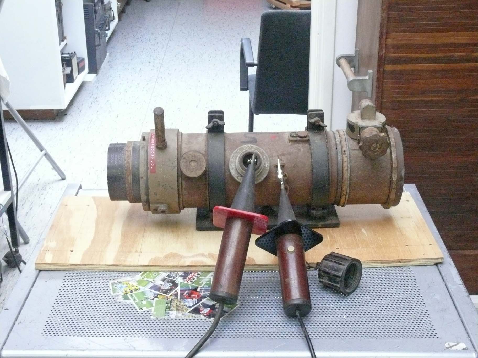
Because we lack an appropriate connector we choose for this experimental means
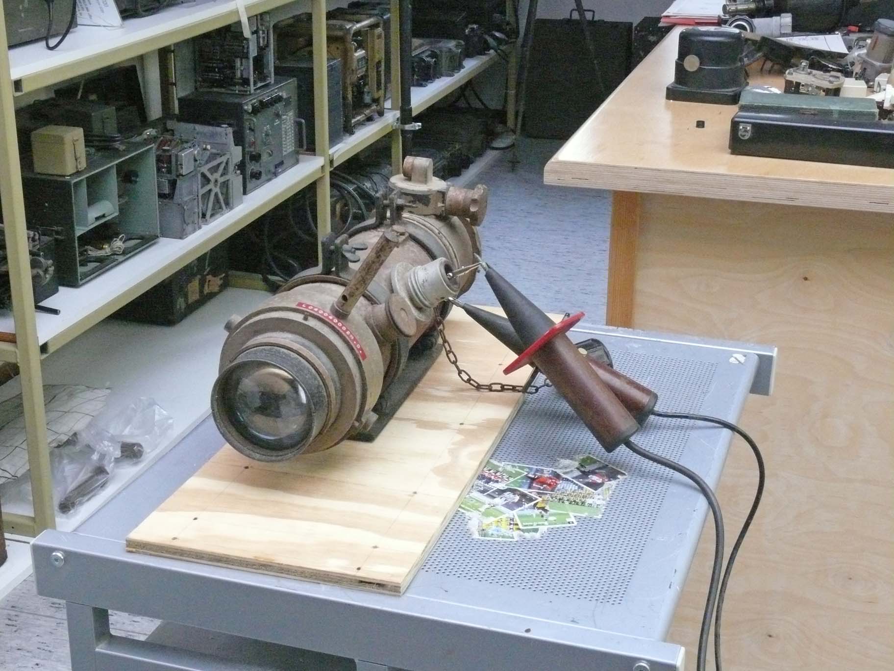
Viewing it from a different perspective

The table has been pushed into our depot, as this space can be completely darkened
It looks a small space, but its length is ca 5 metres deep.

Without Hans Goulooze's support we could not have accomplished these experiments
We are using a wooden plate, which actually is not directly necessay.
He looks a bit sceptical, but he truly is not!

The light source not yet being directed appropriately
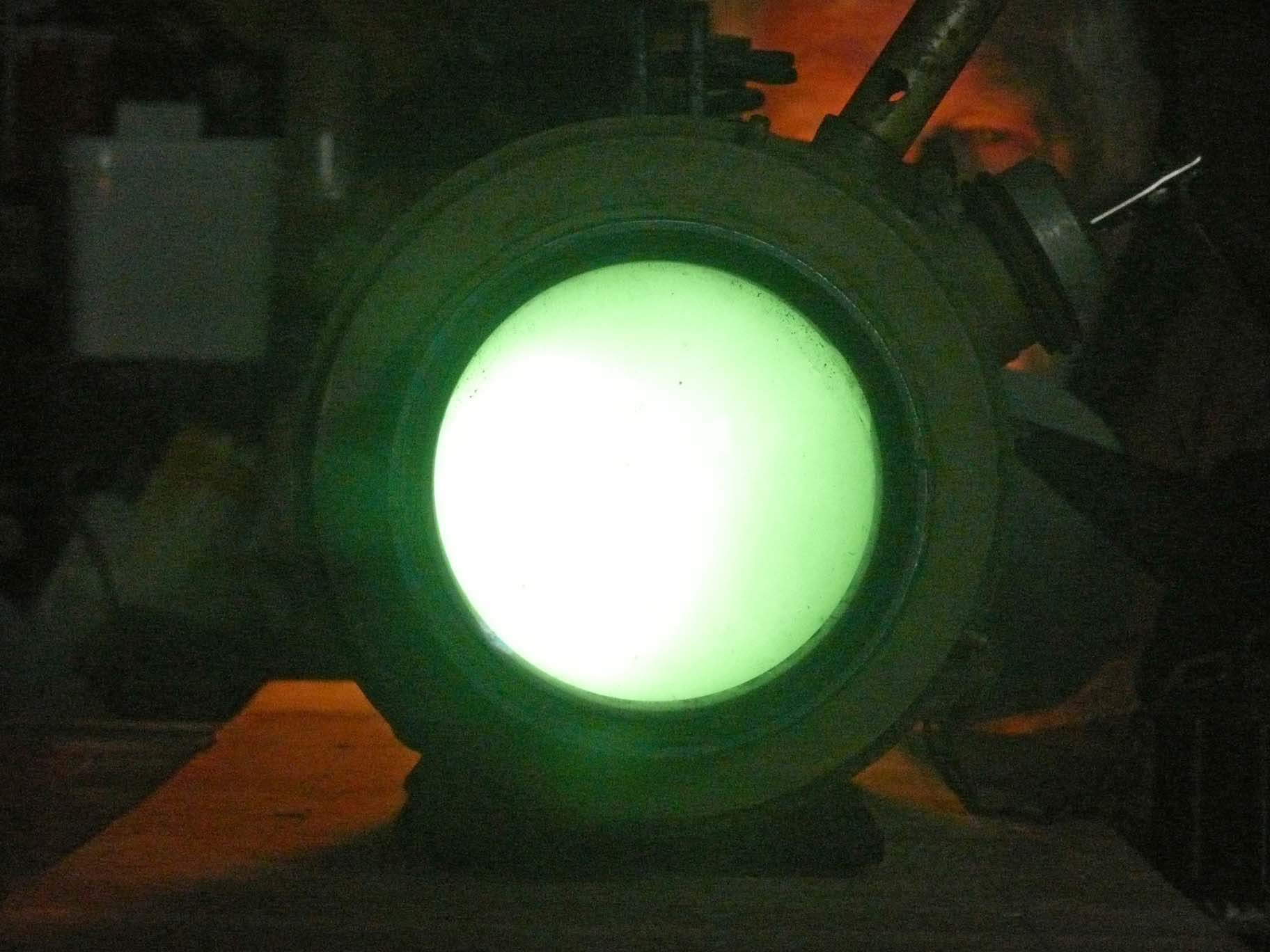
But at least a first sign of life!
Please notice the soft red shining in the background originating from the miniature torch lamp.
Clearly showing the impressive sensitivity of the system.
It has to be noticed that a new series of photos should be taken with decreased camera sensitivity.
However, we also shoot some YouTube films shown next, which does cope far better than our photographic camera.
YouTube films:
Film 0019: Shows the experimental set-up in our depot
Film 0016: Hans Goulooze is holding two matches in his hand. The door between depot and rear exhibition hall is still open, which is visible on the reflections at the the final lens.
Film 0017: Please notice the beautiful after glowing of the match kept between Hans Goulooze's two fingers. This experiment shows extremely well what sensitivity is to be expected.
Film 0020: This experiment shows nicely the spectral sensitivity of the IR convertor tube. The first spot originated from a series of blue led in our torch. Later on hand switched over to a very tiny lamp (bulb) having accordingly low light temperature, but is overloading our IR convertor entirely. What a remarkable experiment. The vertical bar originates from the not entirely shut door, and is accordingly showing the sealing of the exhibition hall.
Film 0021: Viewing the experimental set up in the depot. Please notice the small torch on the table and the green "magic eye" tube up in the centre of power supply (below).
Film 0022: This experiment is performing wonderful. First the depot illumination is on, then switched off. Followed by experiments with the three modes of the torch: only two led on - then 4 leds on (full) and then the tiny glowing lamp being on, which latter is clearly overloading. Please notice during the last test on the far right-hand side you will notice the blue cloud like lines, indicating the shining of the leds in the torch.
(2)
Monday 21 January 2019
Today together with Alfred Breur we went to the Museum and started up our experiments again. This time using a Philips so-called: "Infraphil" infrared treatment lamp.
YouTube films
Film 0023: The first experiment operating the Philips Infrared lamp. You will admit that the shelf is very well visible, also the tools and other means.
Film 0024: This time Fred hold the lamp in such a way that the light beam is about in line with the main apparatus cylinder. We also reduced the lamp voltage supply and later increased its supply.
Film 0025: This time we have increased the supply voltage up to ca. 170 V.
Film 0026: Now lamp supplied at 60 V, still the shelf and what is laying on it.
Some image photos
We are viewing at the final lens

The white/grey vertical lines, actually are constituting reflections, originating from the door behind me which is not kept entirely closed, separating the depot from the rear exhibition venue

It is evident that the Infraphil lamp is standing on the left-hand side
(3)
On 11 February 2019
Today we would like to show you some quick experiments commenced with a gift on behalf of Remco Caspers.
It concerns an infrared spotlight; which he once got from his late father Cas Caspers
(PA 0 CSC)
He wrote: that he vividly remembers, his father's experiments, when he was aged about 14. His father used it in a dark corridor when he experimented with a Seehund infrared vision device, of the German wartime Navy. Both men were delighted with the results.
In the German manual it is expressed that infrared spotlights are quite dangerous devices, because in the nearby range a small portion of the light still being noticeable (visible).
However, Remco's spotlight is of a post war type and possesses, likely, a more advanced infrared filter in-front.
As, when being switched on, nothing is noticeable, but my hand, kept in, front warms a little bit up; a clear sign of the existing infrared rays.

It arrived with a canvas cover (in front the on-off push-button)
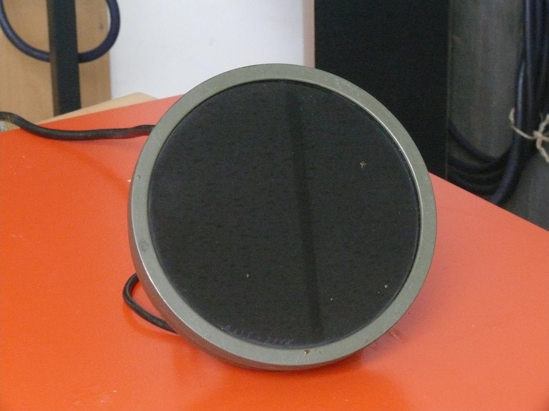
The infrared spotlight with an IR filter in front
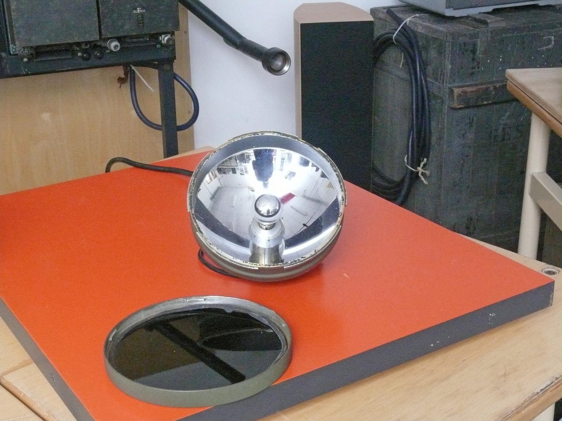
Remco suggested, luckily, that I should look whether there is a lamp (bulb) inside.
I found the lamp inside, though, it needs 5.5 V and consumes 35 W
Not a voltage value which I would have expected.
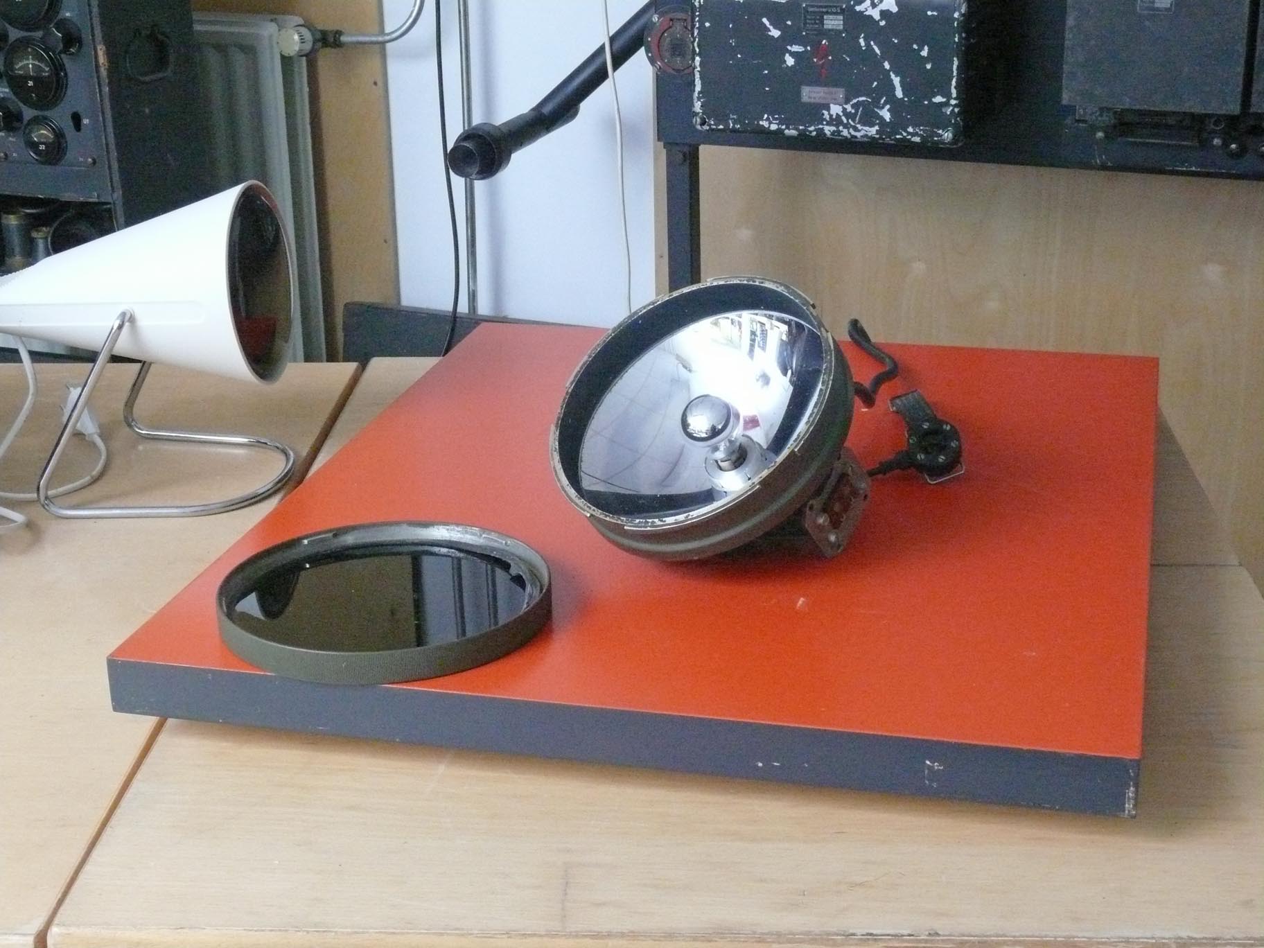
The mirror in front of the lamp, reflects the light into a parabolic mirror, and therefore the device has a quite limited aperture
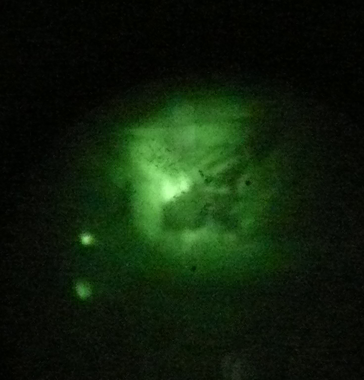
Watching the image through the convertor tube
Maybe you also notice that the beam is circular, but in its centre is producing a bit more light than at its perimeter
Please be aware that we were standing only 2.5 to 3 metres from the shelf, whereas in practice we have to count with a few hundred meters.
The next YouTube film is quite informative.

This photo shows clearly that an over-exposure being encountered at the IR image-convertor
I would like to suggest: that we should first repeat the latter experiment, but now with reduced supply voltage onto the spotlight, so that the shelf detail will be visible again (preventing overloading the infrared image-convertor tube).
I would not wonder that we have to go down to about 4 V supplying at the lamp (bulb) filament.
YouTube film:
Film 0027: This time we are illuminating the rear shelf in our depot, its light-power being too intense for the IR image convertor sensitivity. Which was designed to cope with distances of up to, say, 400 metres in the operational field; whereas in our depot we have only 2.5.- 3 metre free space available. This experiment is only commenced as to show what kind of vision is accomplished.
From our experiments, we may derive, in our case: that broader field illumination is favourable, then spot illumination. The best results have been obtained during the application of an Infraphil light-source (albeit, with strongly reduced filament power, down to ca. 70 V à 80 V). But far off observation necessitate more a powerful light source, and an IR spotlight may well be then a good option.
To be continued in due course
By Arthur O. Bauer
![]()