
Der Zeitdrucker 38
Page 2 of this series
One of the many artefacts we kindly got from late Graham Winbolt.
How it was operated is for us still a closed book. This apparatus although, in a quite poor shape, is intriguing me as it should measure the time difference between a range of sensors as to pinpoint the position of artillery or its impact? Presumably, of their own (German) artillery.
Status: 25 October 2013
(2)
(1)

We have not been able to find a 'type number plate', what is found is a schematic inside, designated as: Zeitdrucker 38 (time-printer) and manufactured by NT (Normal Zeit, once owned by AEG, well known for their Train Station Clocks)

The Zeitdrucker 38 schematic
For getting it in PDF format, please click on this schematic
Please notice the punch-card with holes down in the centre of this schematic.

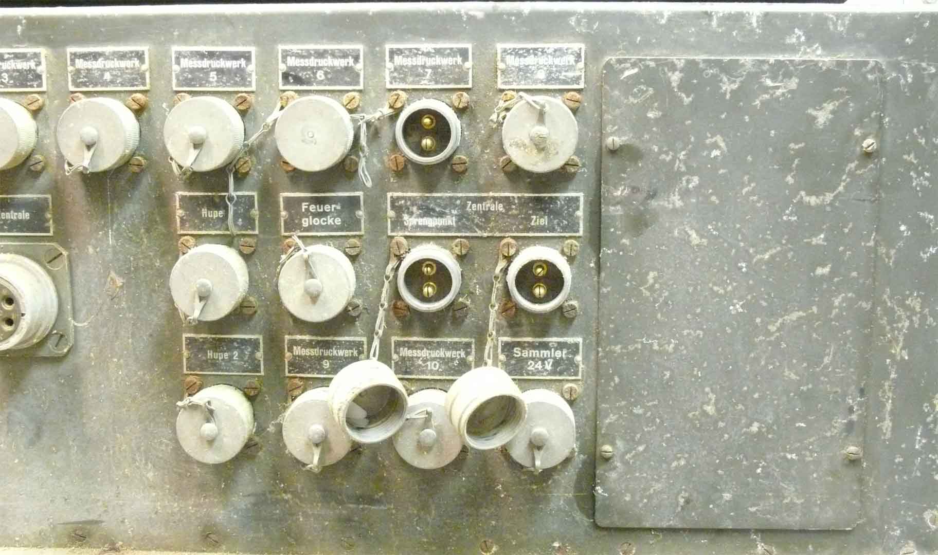
The what likely was called: Bedienteil (control panel)
The one out of the five punched-cards below should be selected and be put over the two guiding pins in the upper section of the control-panel. Each card represents a particular operational mode. (the cover being removed)
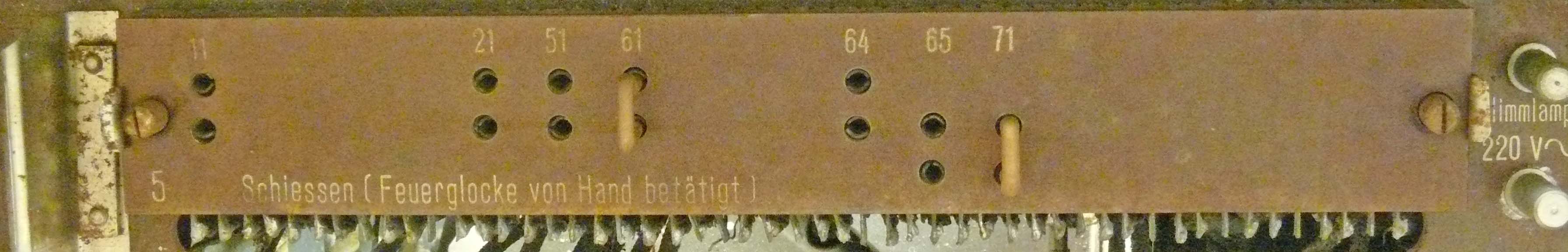
For this occasion one program-card was taken and two bridging contacts being inserted
Program text: Schiessen (Feuerglocke von Hand betätigt)
On the upper right-hand side just visible a mains connection for feeding a neon bulb. Most likely for controlling speed against the mains frequency of 50 Hz.

The way the contact-bridges being kept inside the control panel door

The 5 program-modes punch-cards
The programs in inverse succession
5 Schiessen (Feuerglocke von Hand betätigt)
4 Schiesen (Feuerglocke durch Zeitdrucker gesteuert) Schalter für Ladeverzug richtig einstellen
3 Opt. Erprobung mit Messtakt ohne Ladeverzugszeit
2 Opt. Erprobung mit Messkontakt mit Ladeverzugszeit
1 Opt. Erprobung mit Messtakt ohne Ladeverzugszeit Schalter für Ladeverzug ??
Deriving from the text this machine is to measure or control artillery 'firing' data.
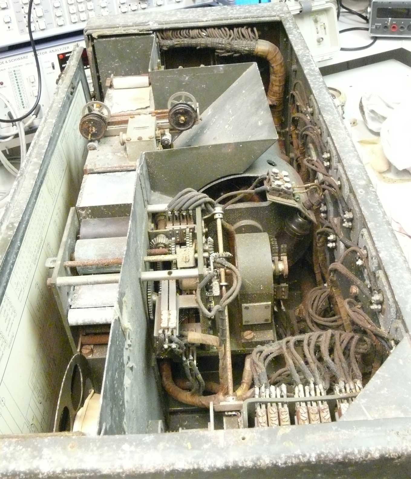
Viewing the machine from above
On the left-hand side we notice the printing compartment, on the right the electro/mechanical section.
Let us consider the printer section first
The printer module

The printer 'head' being released upwards
The type-ribbon is just in front of the symbols. Each character is activated by means of a hammer underneath the paper-tape forcing the paper locally upwards.

The type-ribbon being pushed downwards a bit making the choice of characters visible
(2) Also providing a slightly better view at the 'printer hammers'. When you look closely: the open section at the left-hand side is having a selectable number array! When you look now to the purple block left of the printing hammers, it appears in my brains that this block is also having a hammer function as it pushes the paper upwards for touching the generated sequence of numeral digits. This is in fully accordance to the second photo below!
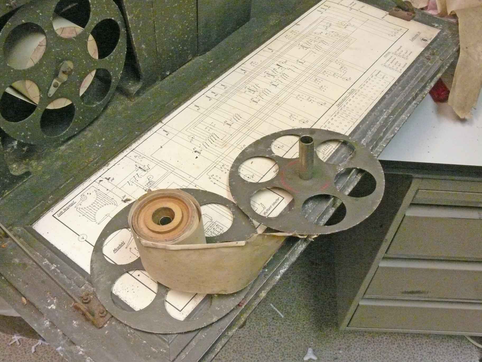
On the far left-hand side partly visible the fresh paper-tape, in front the opened reel with 'used' thus carrying printed data

What the meaning of the figures are is unknown to me. It might be genuine German data, or British post war test results
Please notice my explanation above (2)
Please bear in mind, that this apparatus is coming from the UK. Most German gear was in some way or another tested before it was scraped or disposed of. Considering (2) it may well have been that what actually was printed was done in the UK after the war ceased; or when this device was captured on the continent.

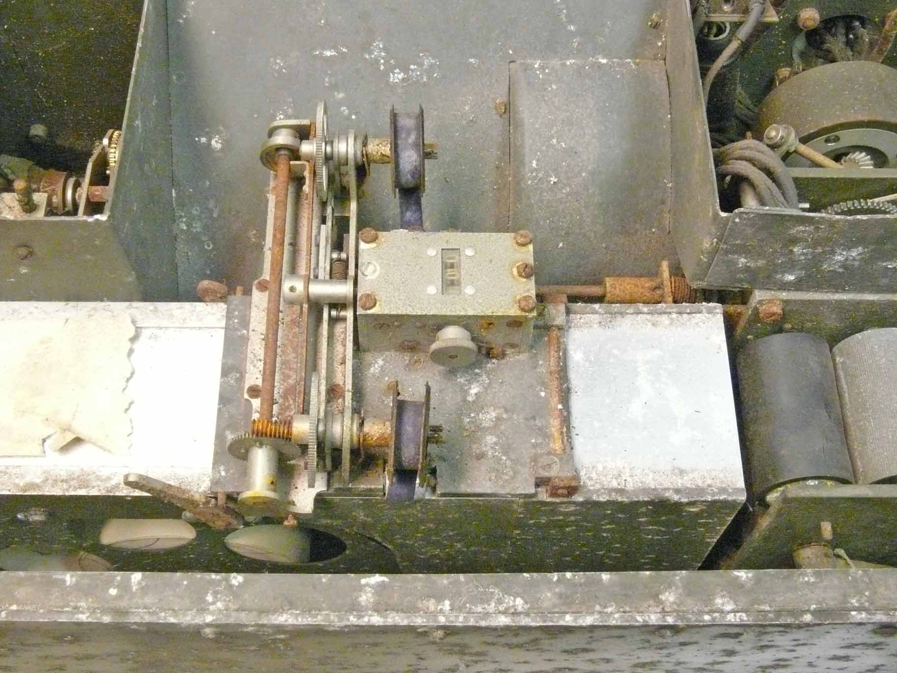
Parts of the gears and clutches
Down on the far right-hand side we see the quite heavy motor, which likely used a 'governor' with which the speed is controlled against a neon bulb fed from the 50 Hz mains. Not unlikely when this apparatus had to measure 'timing'.
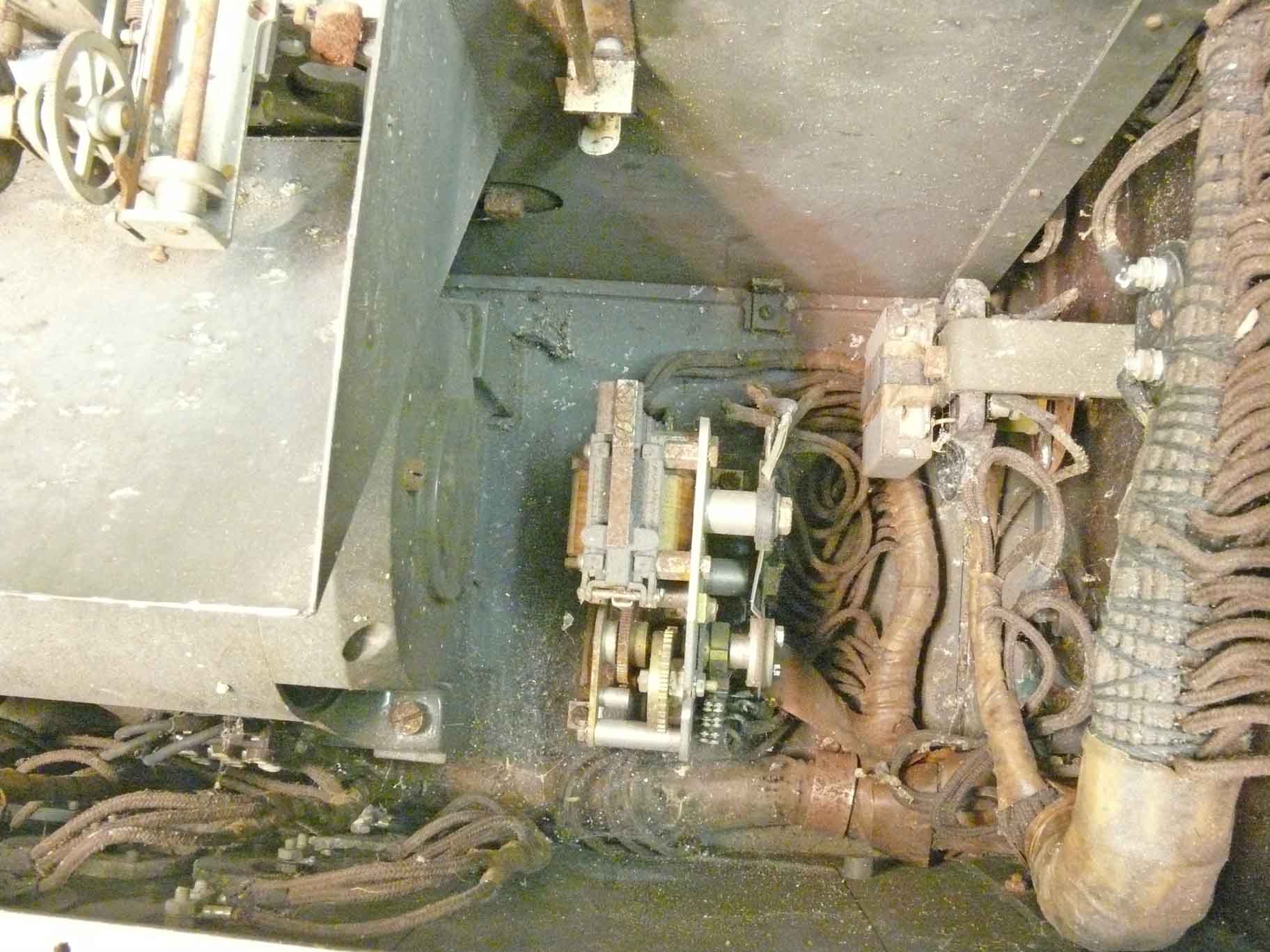
A stepping relay?
On the left the motor, most likely running at 24 V volt. On the right-hand site the wiring of the control panel.

The relay section access
Some connectors made free
It is apparent that interconnecting cabling was for most purposes based on 'two wires'.
Please continue with page 3 on the: Hypsometer
Return to the general first page: late Graham Winbolts artefacts
![]()